The Antique Wrench Patent Archive

Every grip the nineteenth century took on a nut

All 140 patents

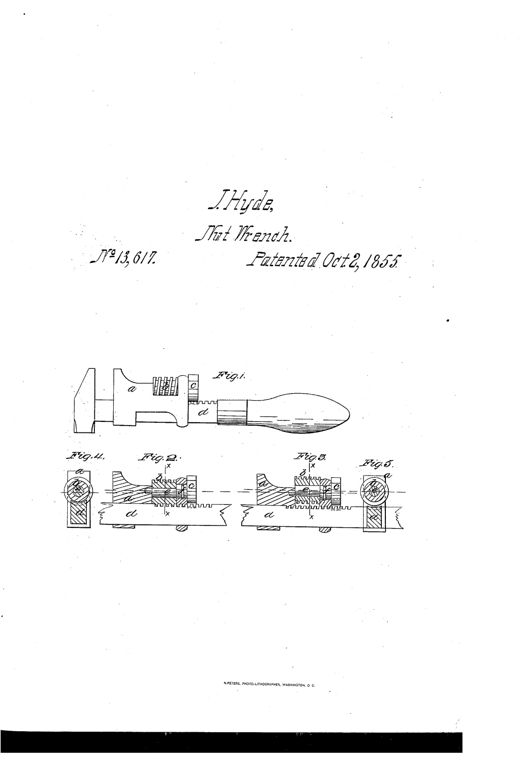
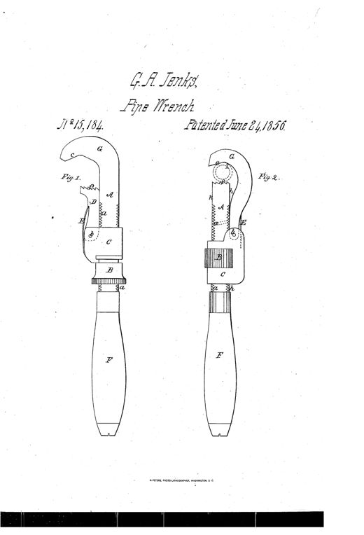
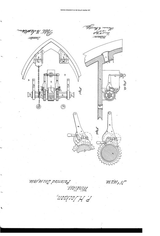
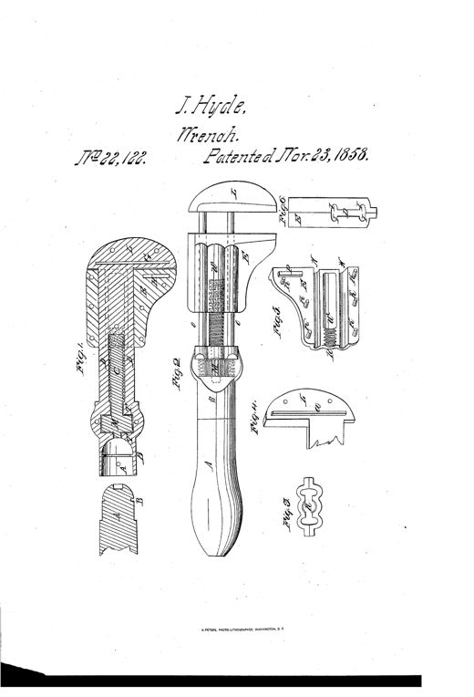
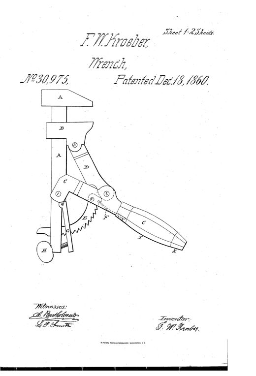
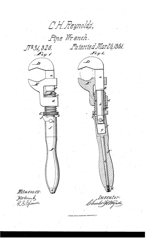
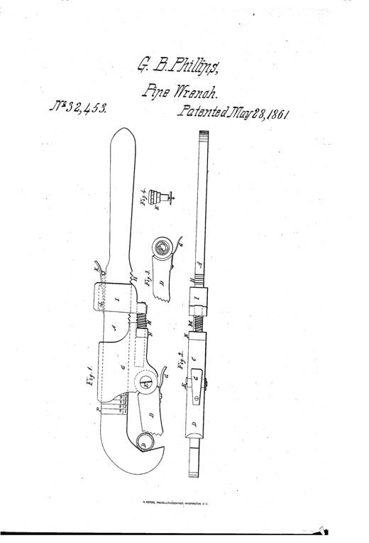
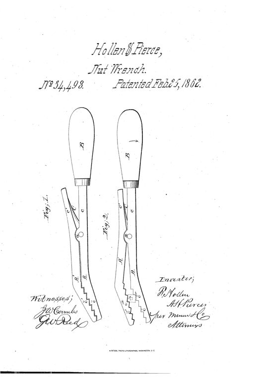
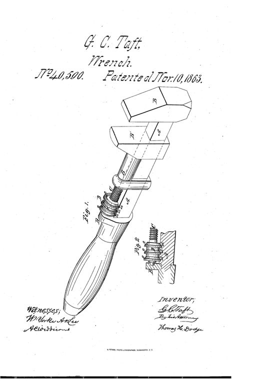
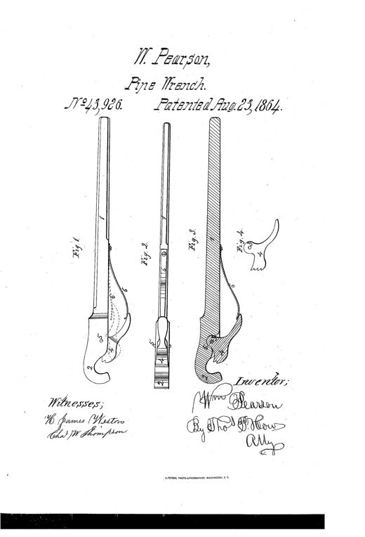
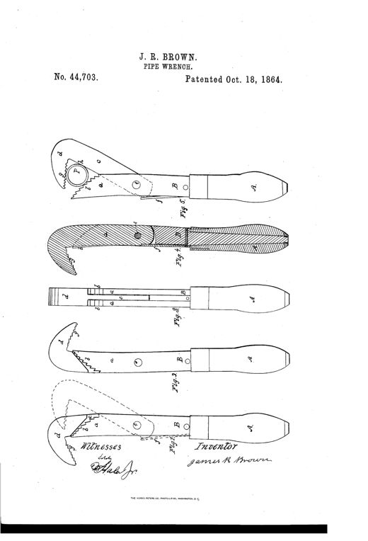
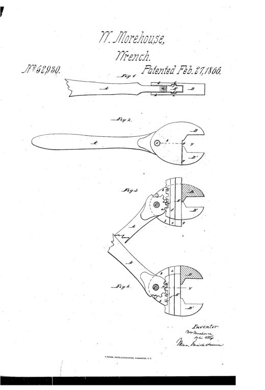
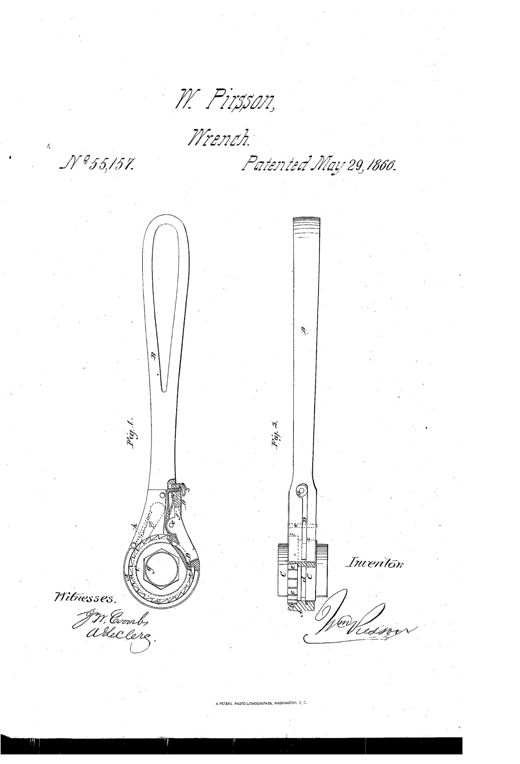
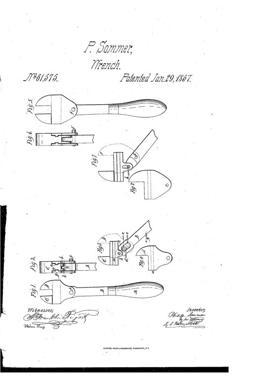
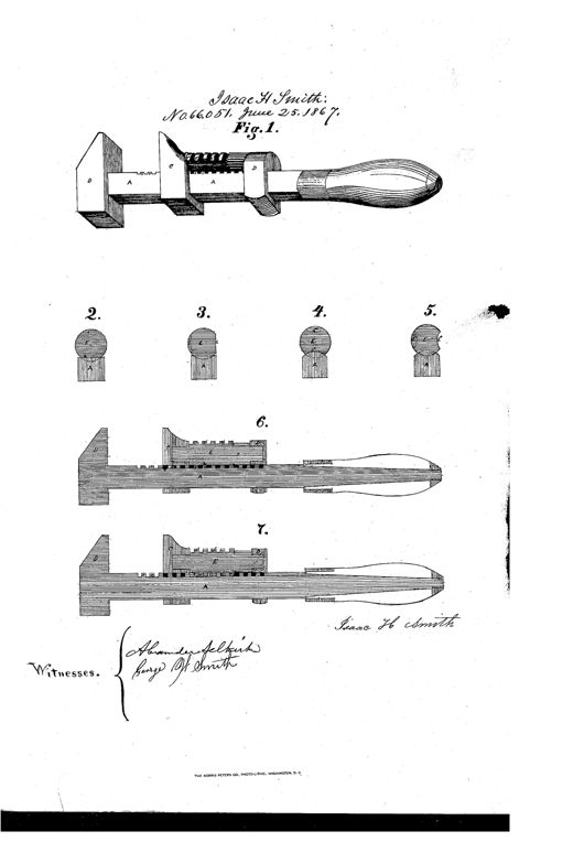
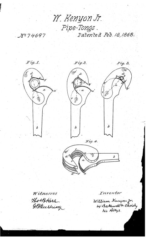
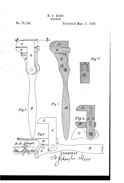
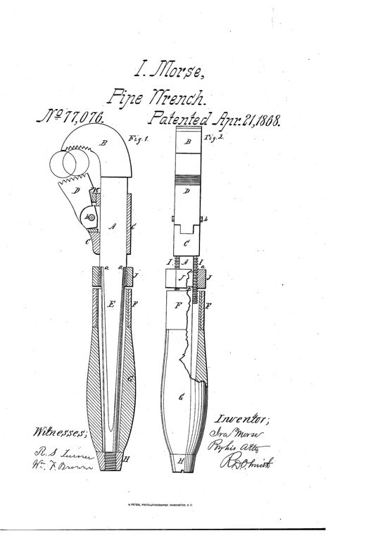
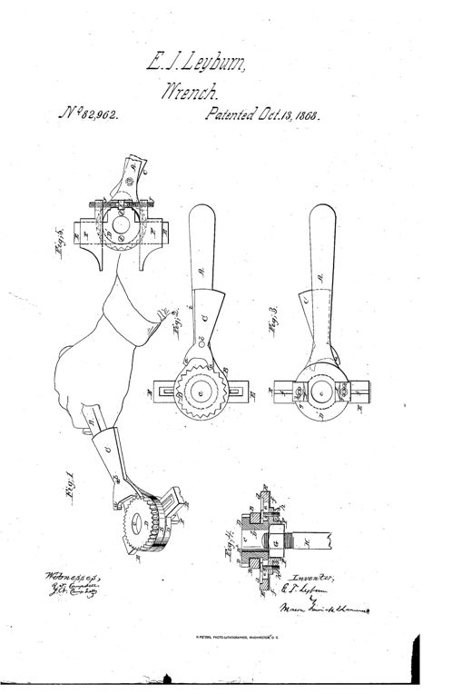
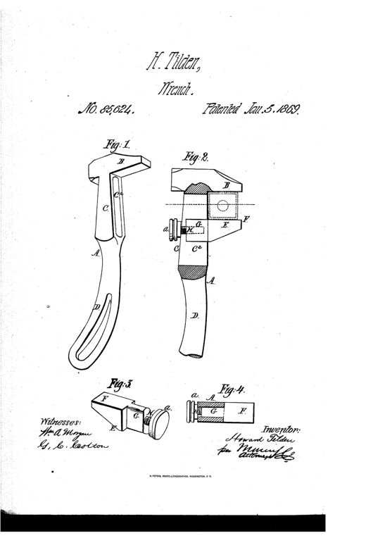
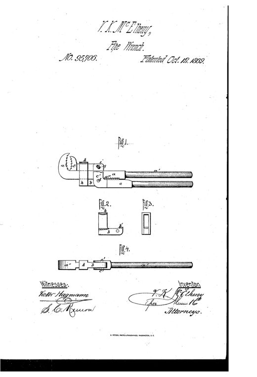
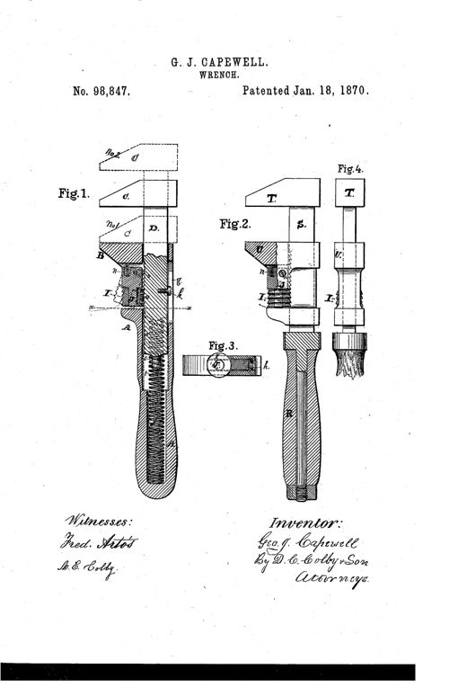
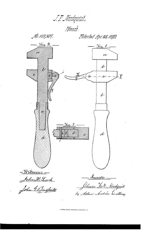
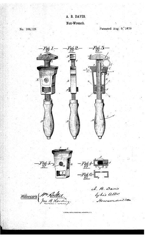
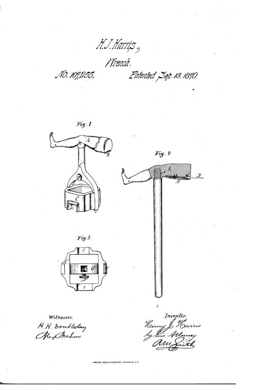
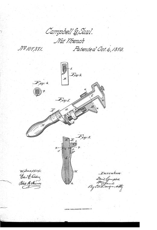
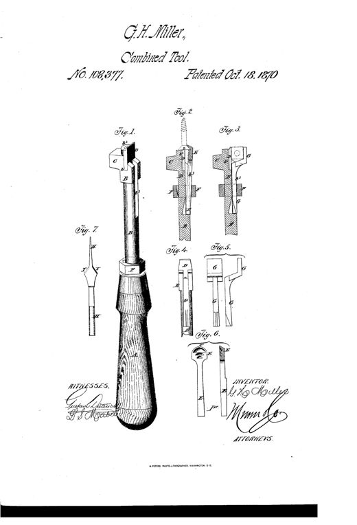
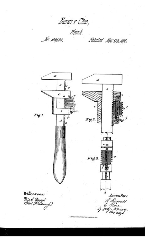
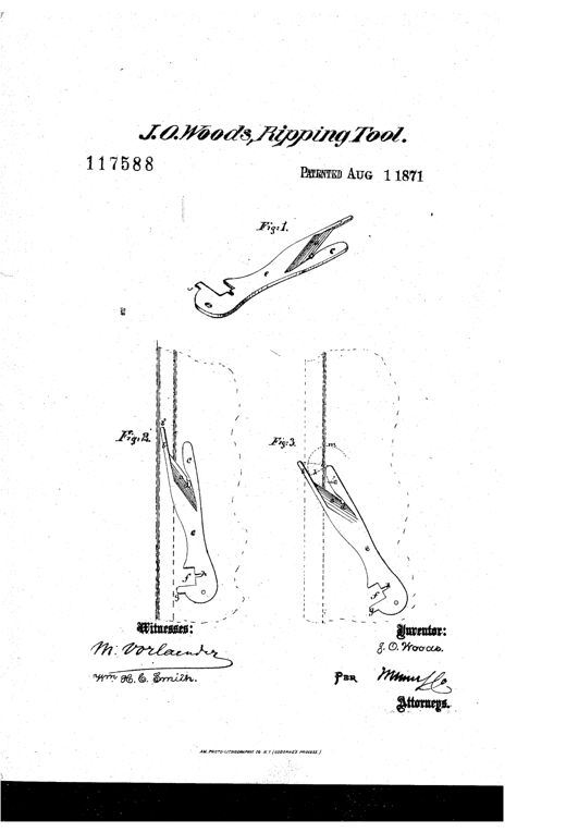
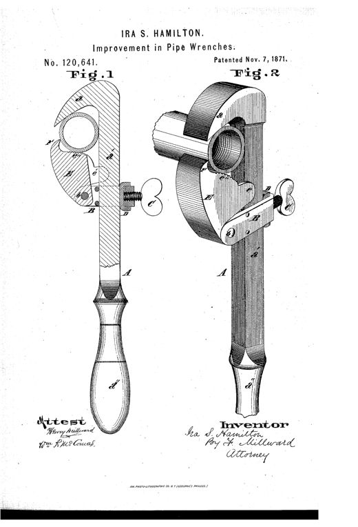
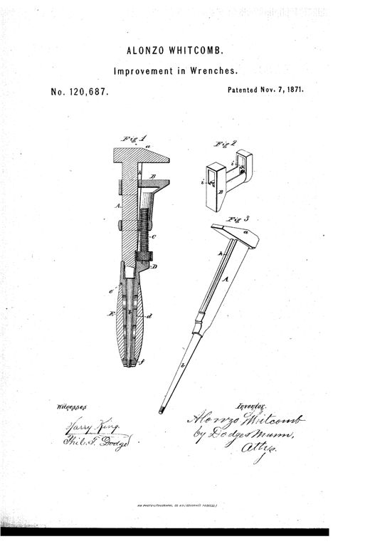
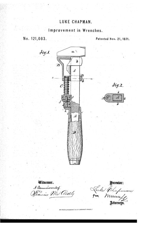
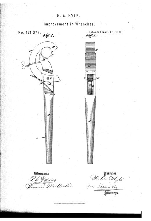
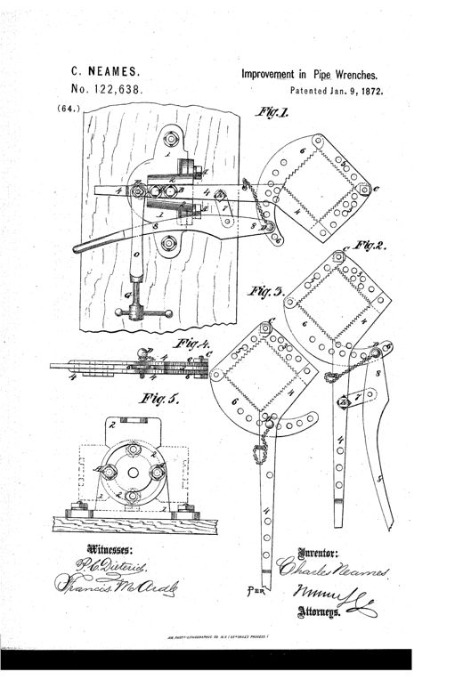
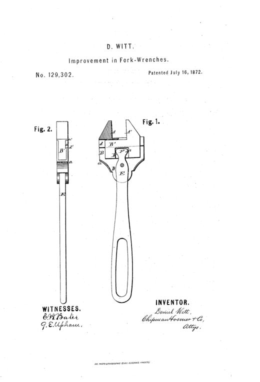
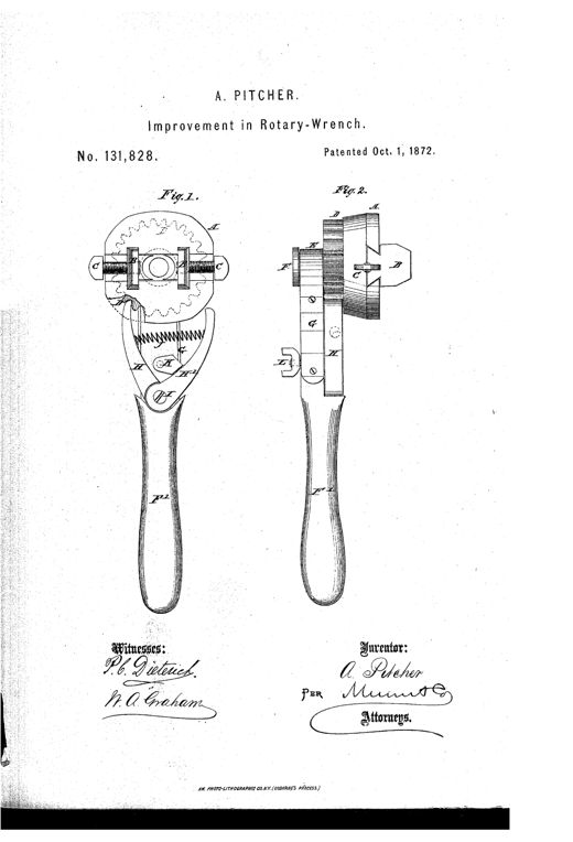
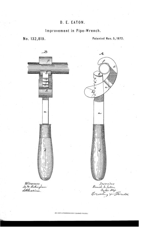
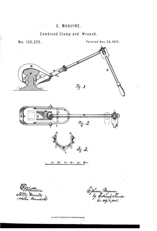
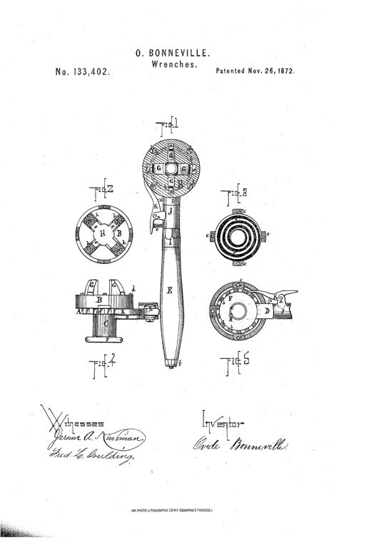
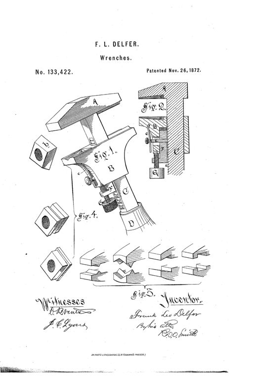
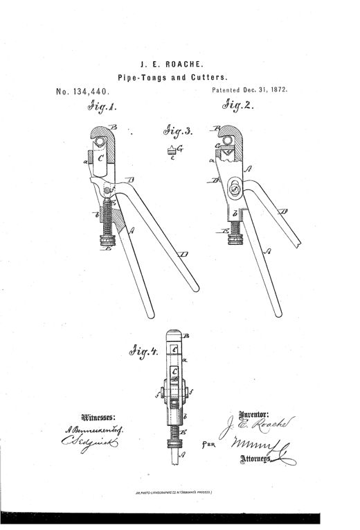
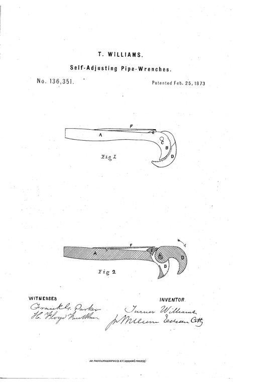
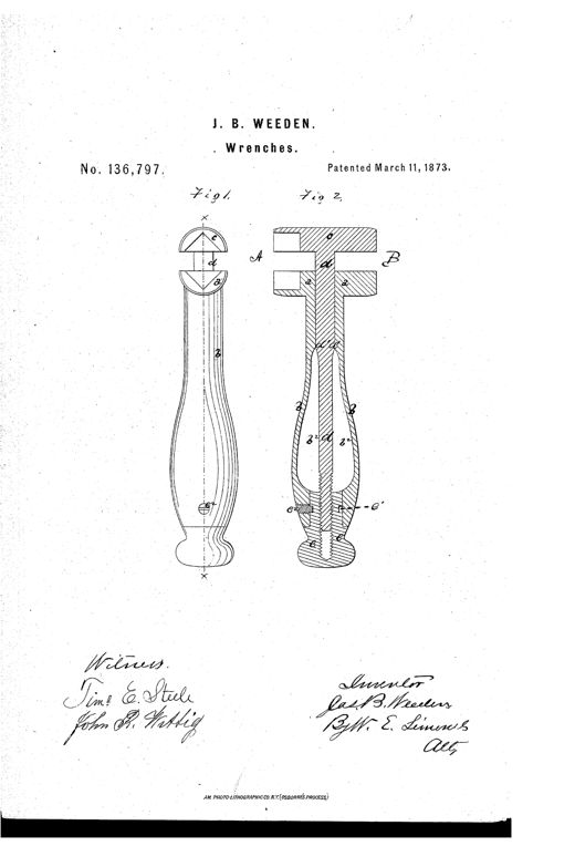
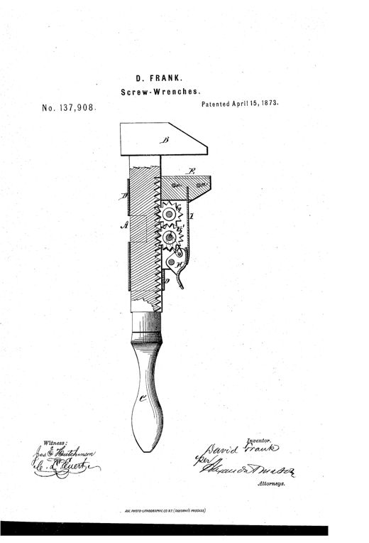
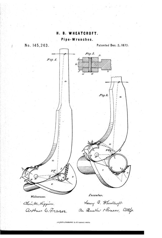
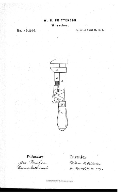
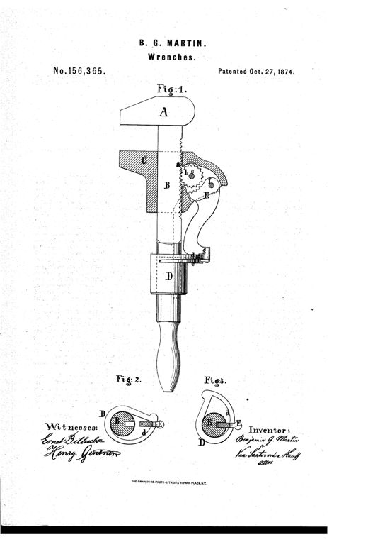
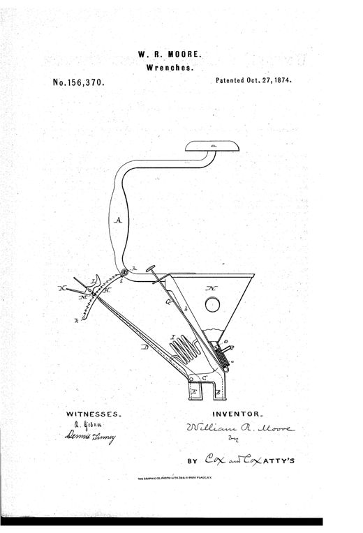
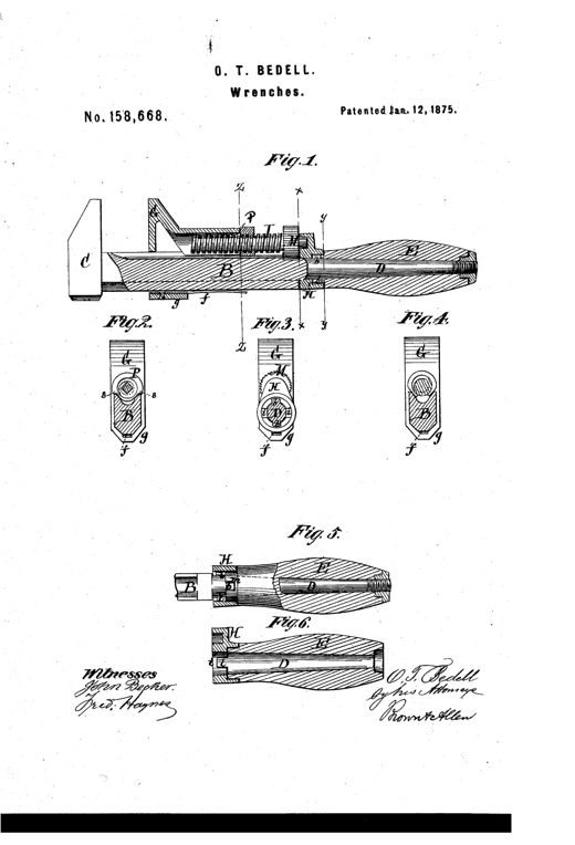
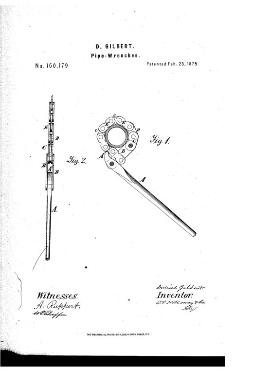
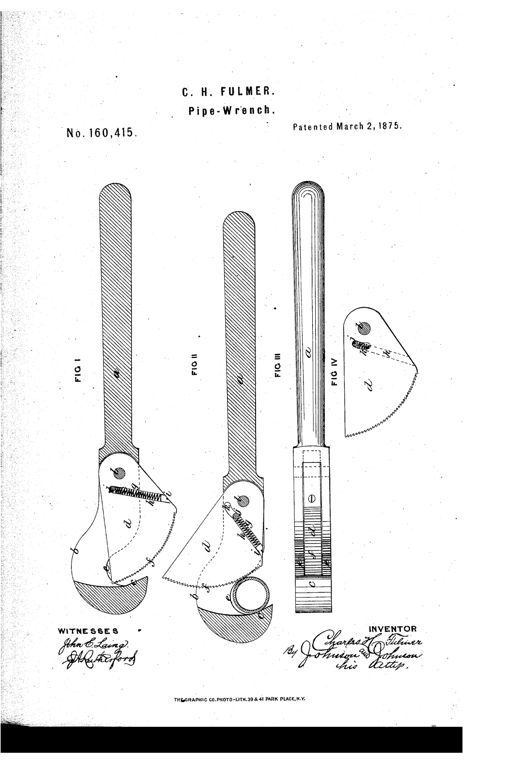
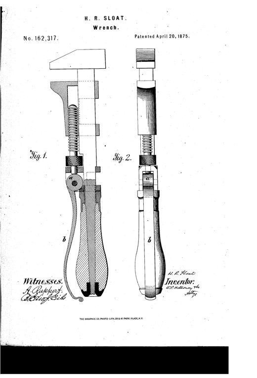
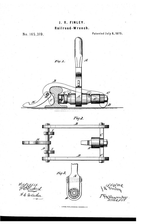
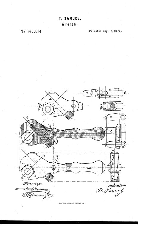
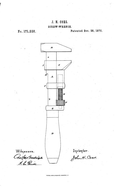
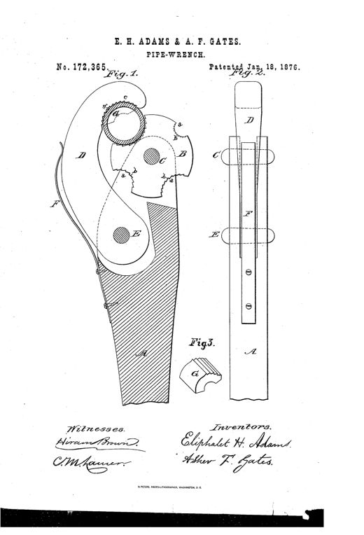
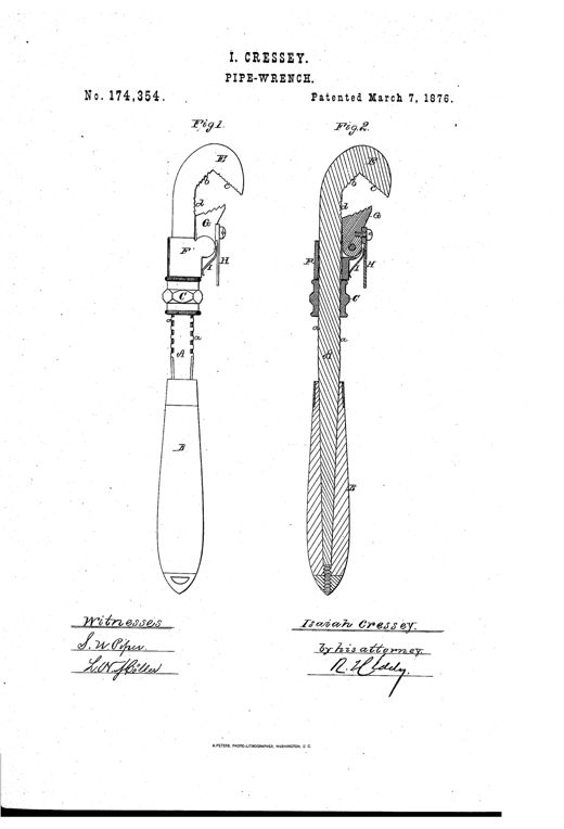
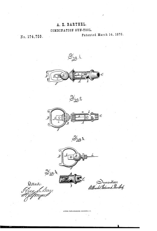
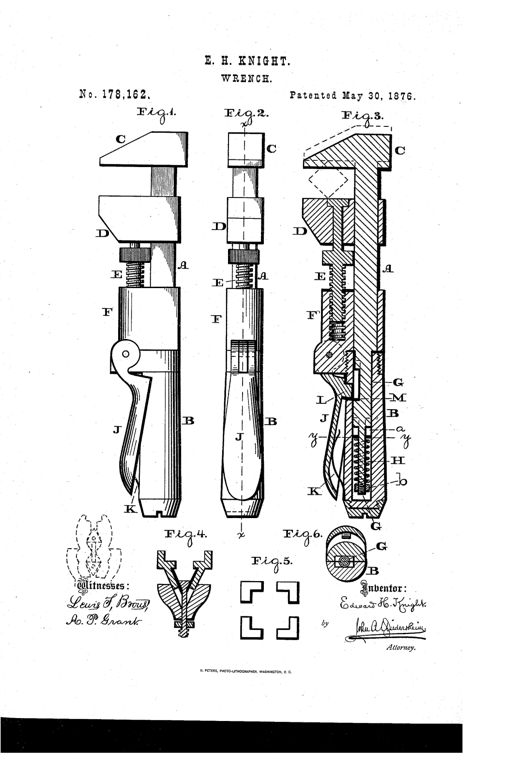
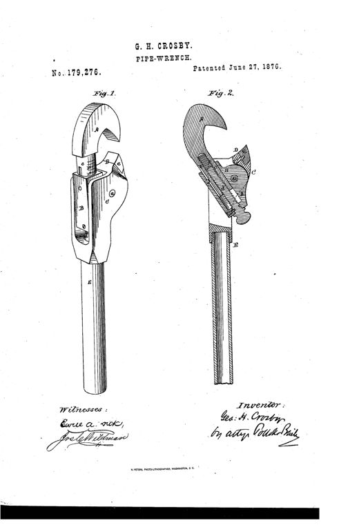
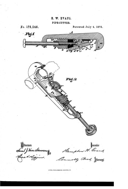
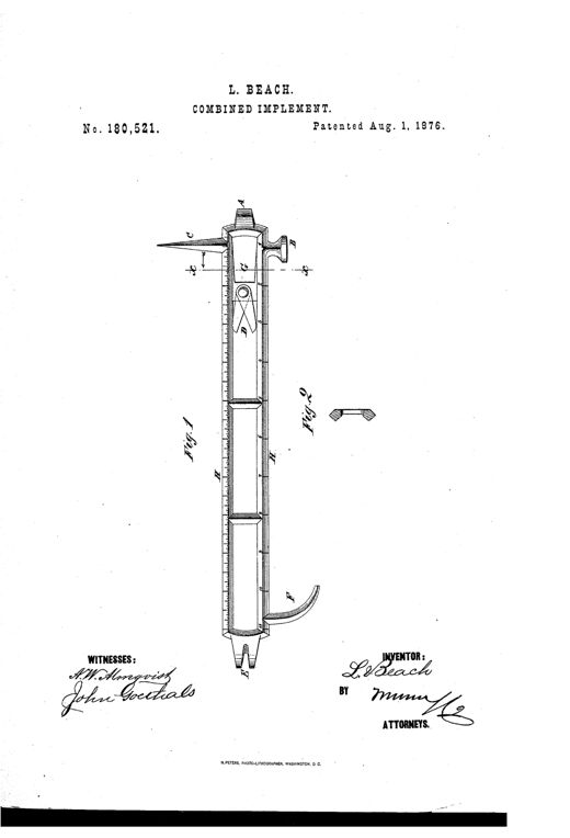
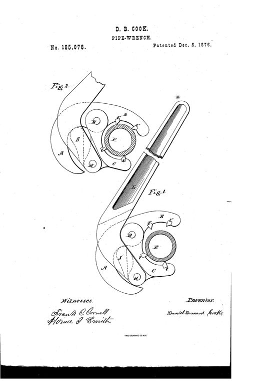
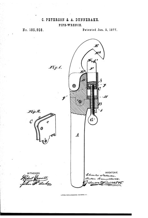
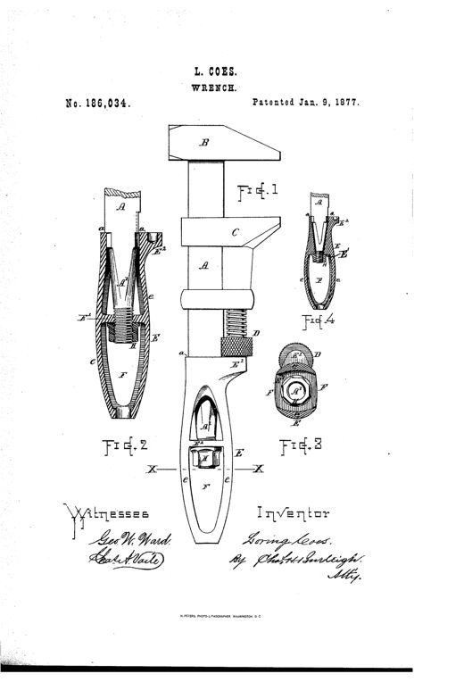
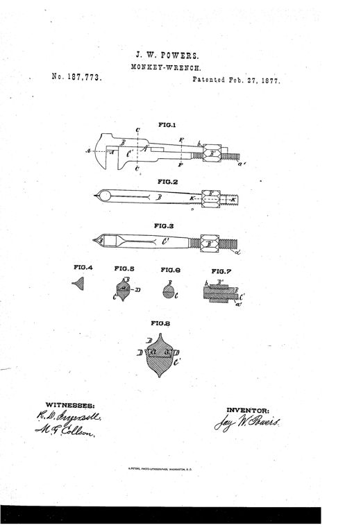
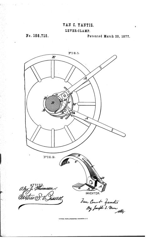
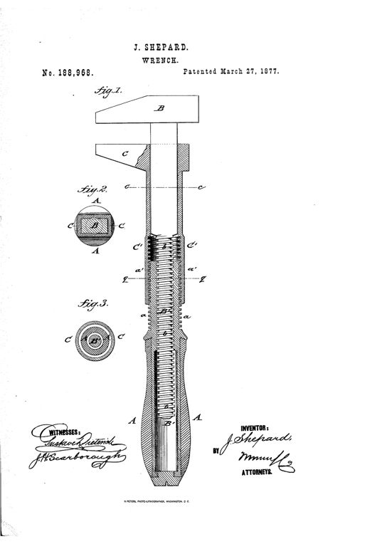
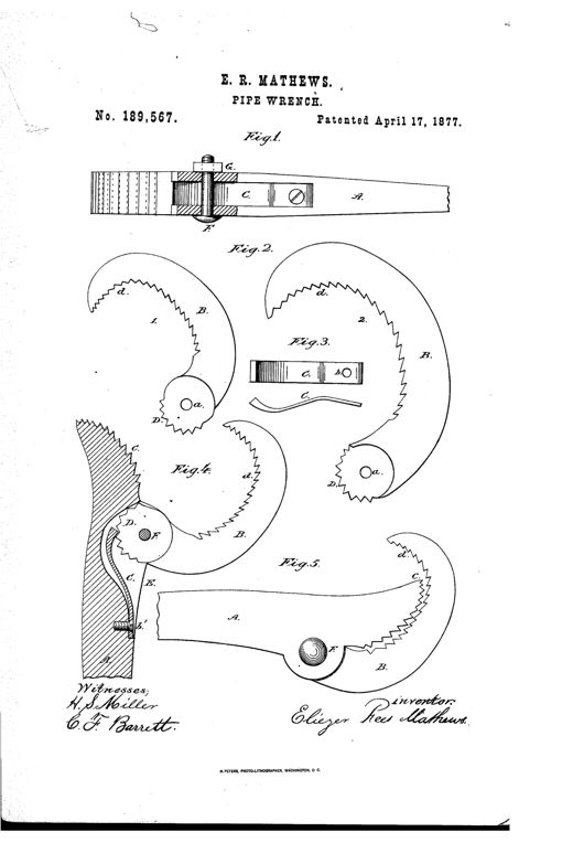
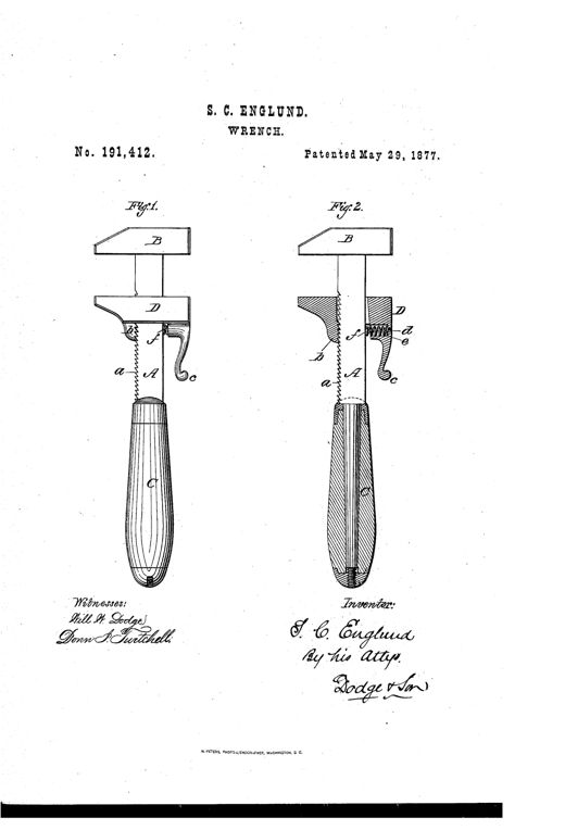
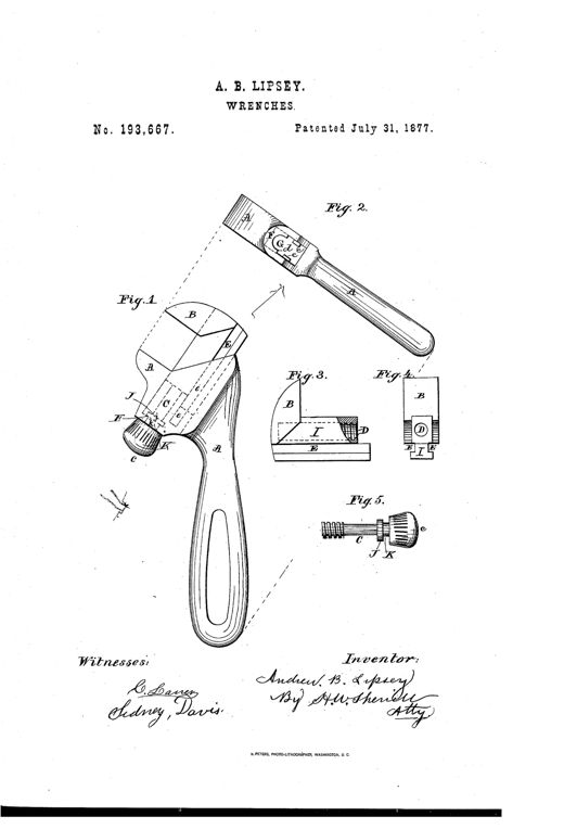
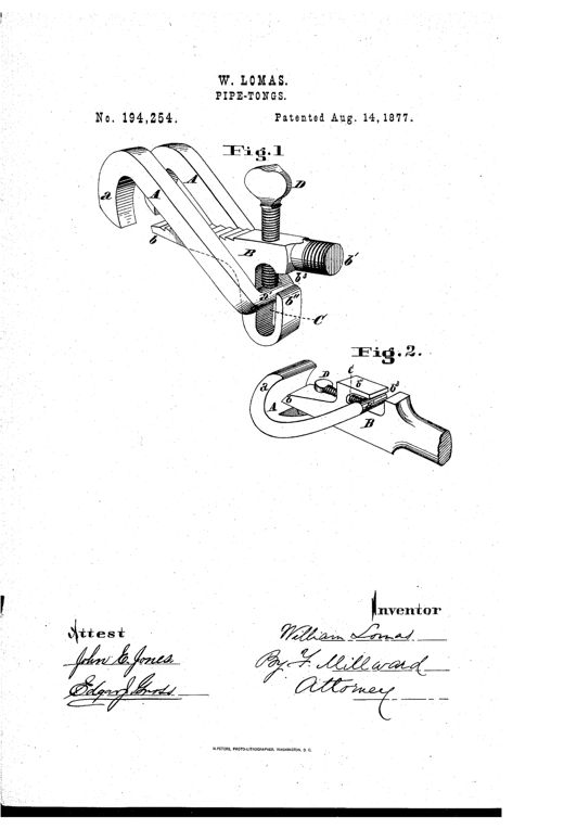
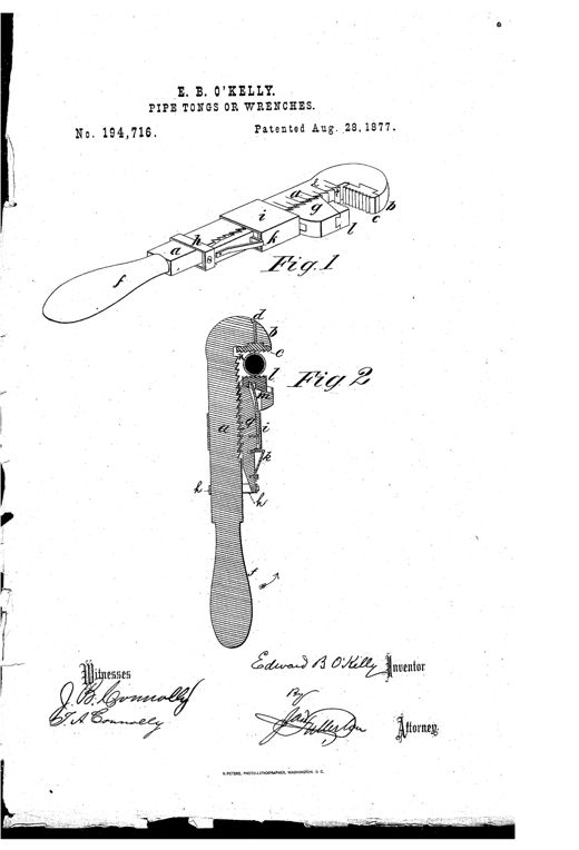
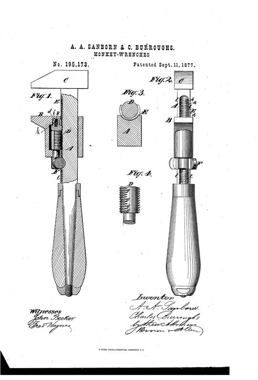
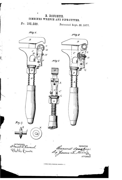
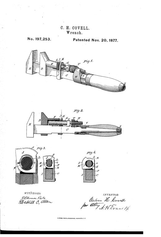
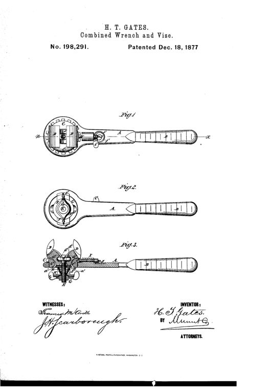
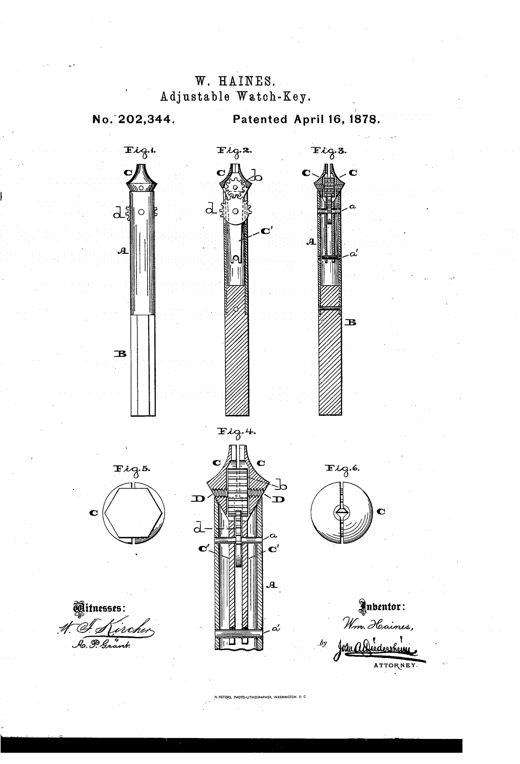
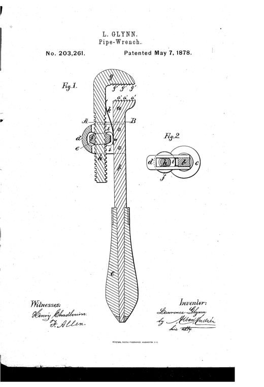
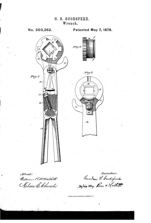
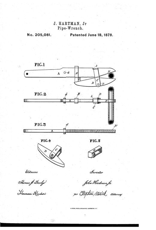
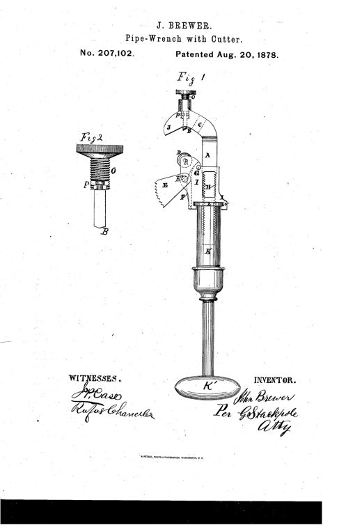
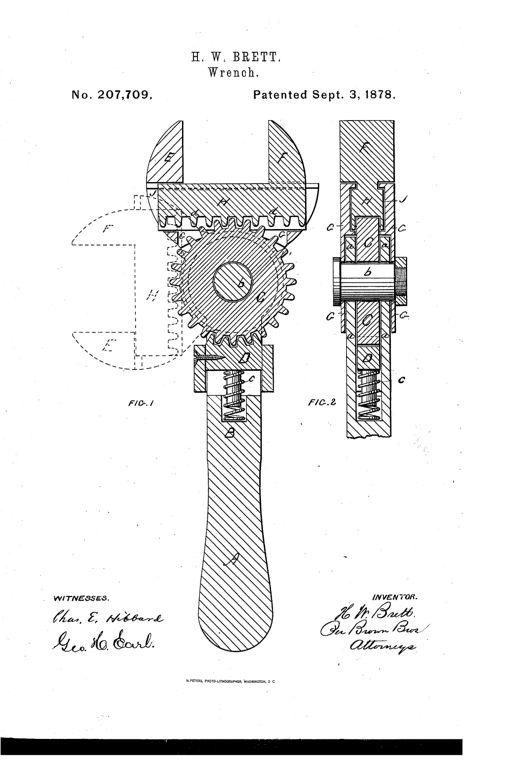
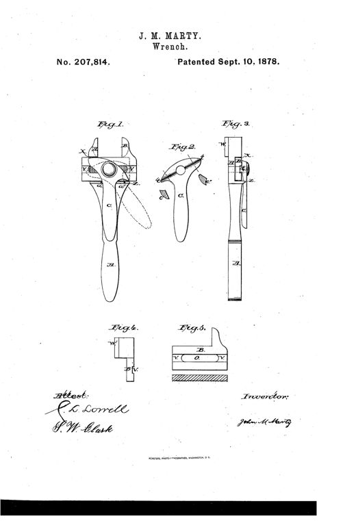
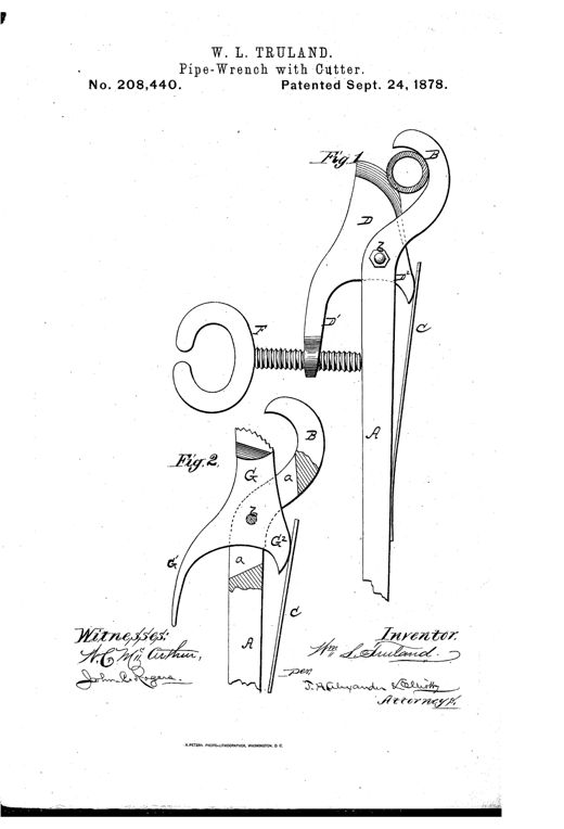
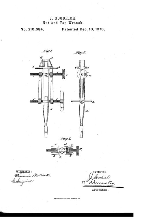
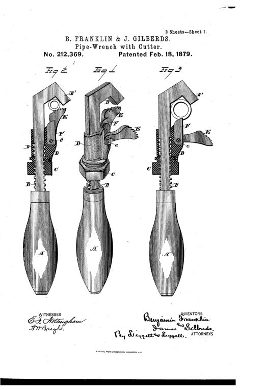
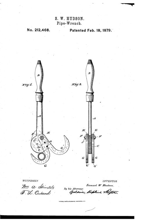
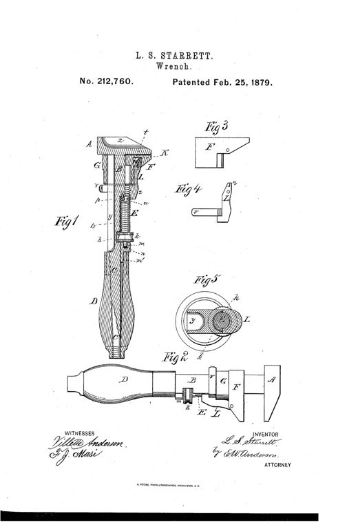
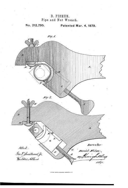
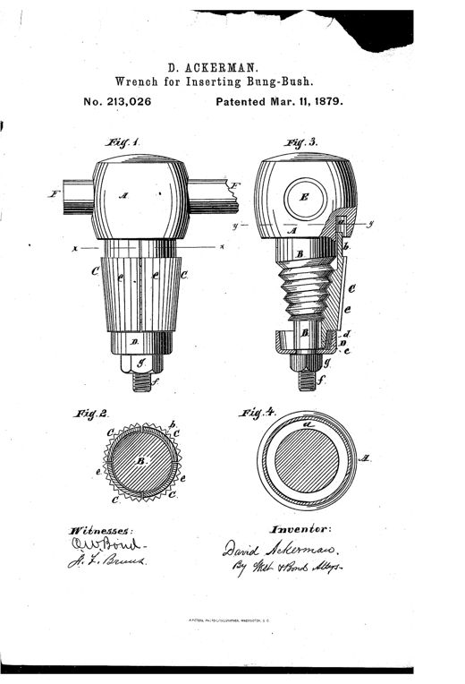
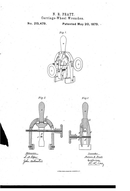
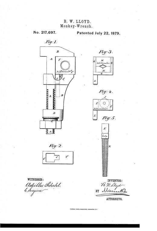
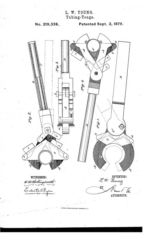
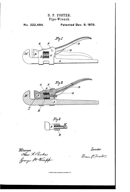
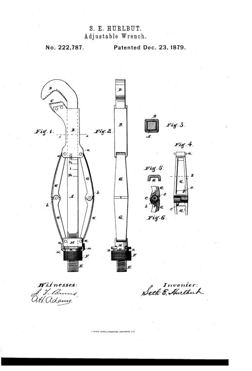
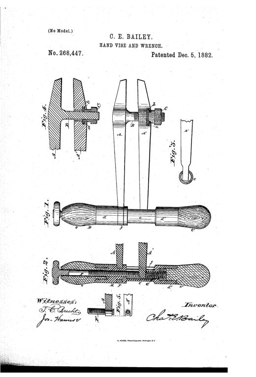
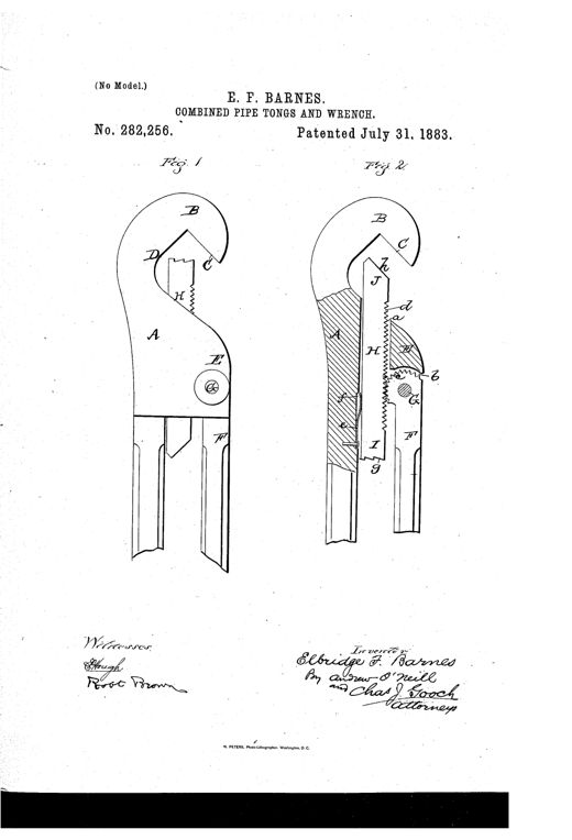
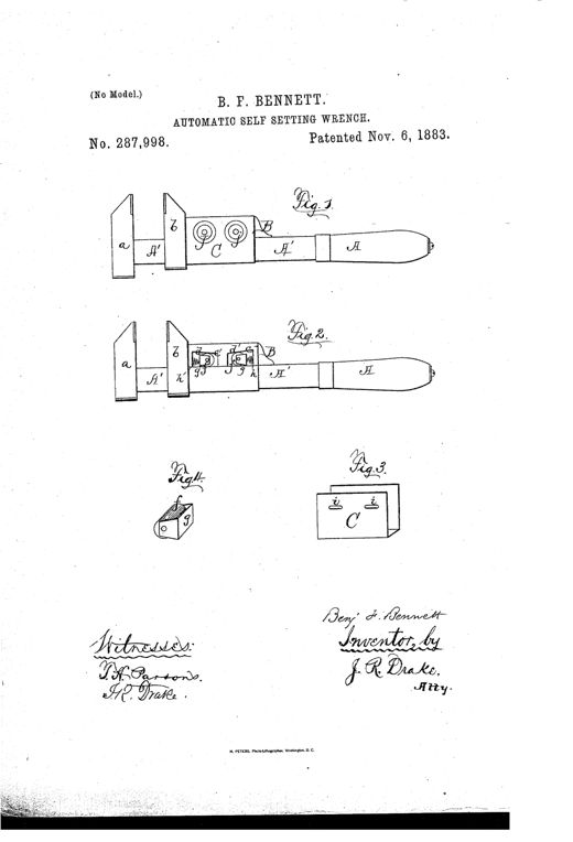
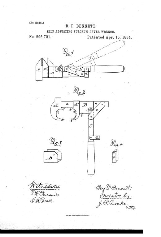
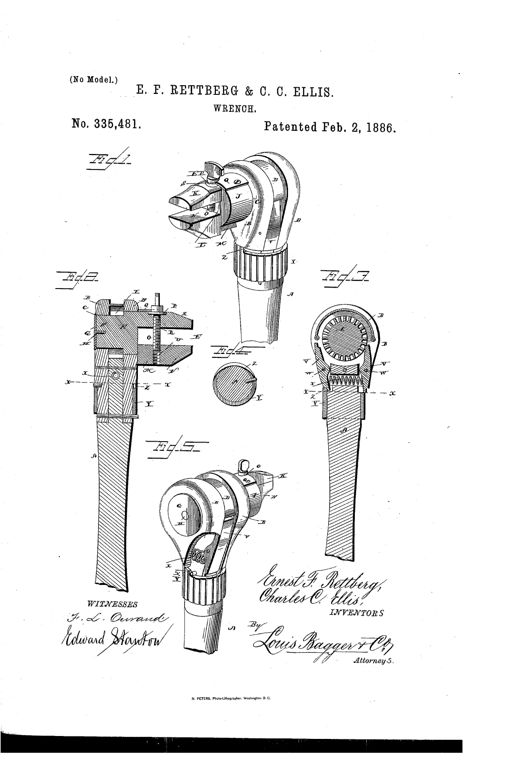
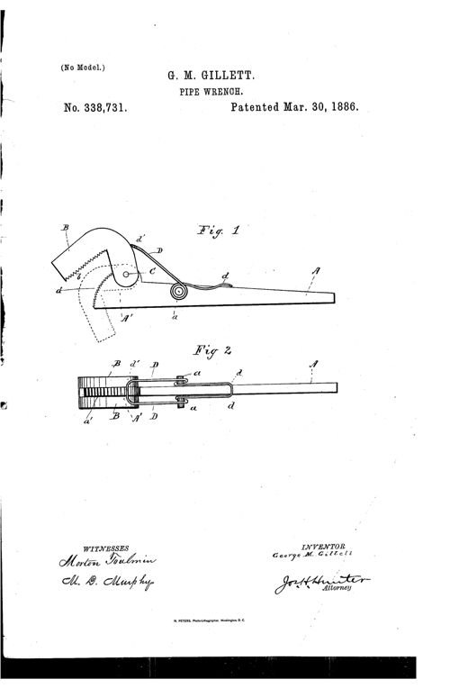
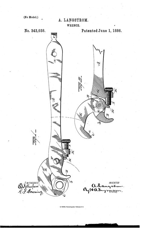
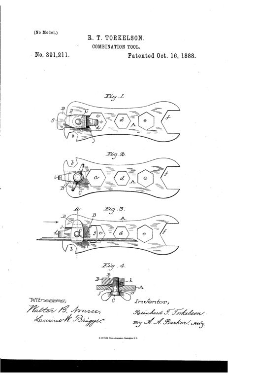
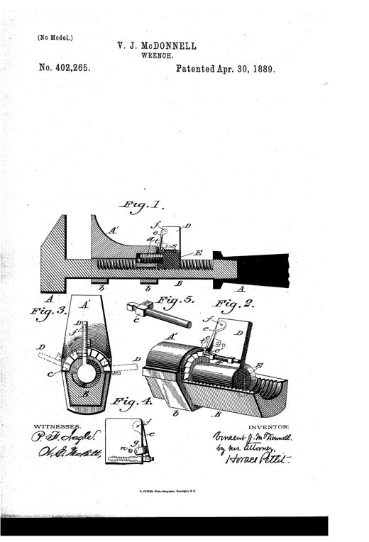
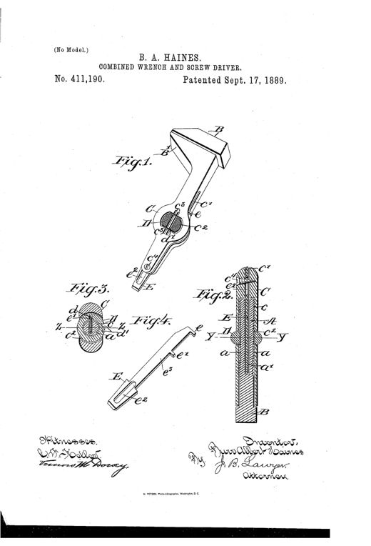
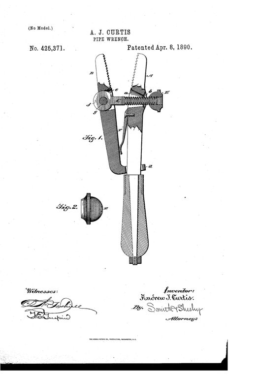
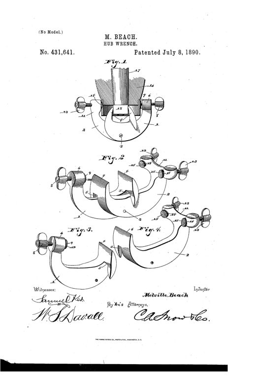
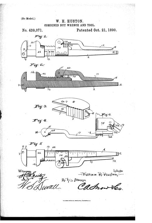
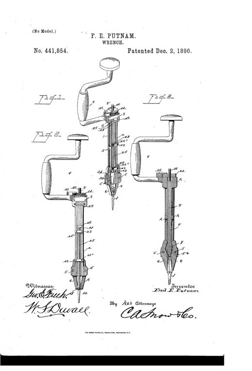
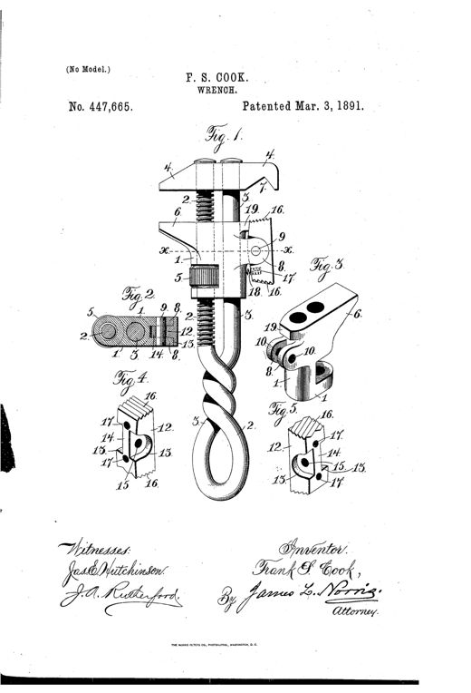
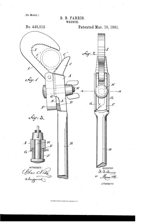
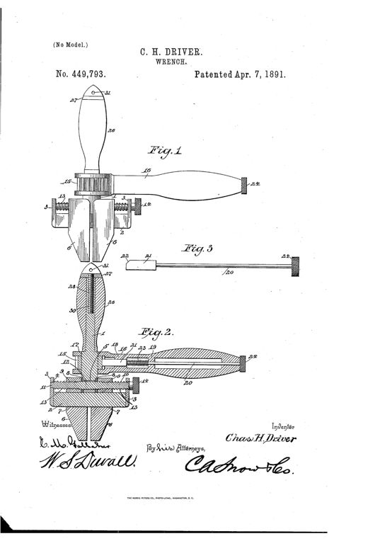
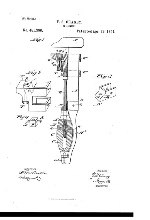
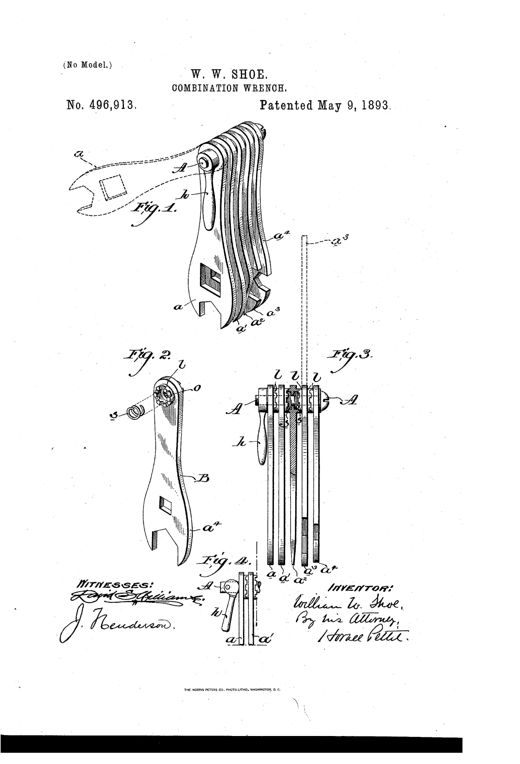
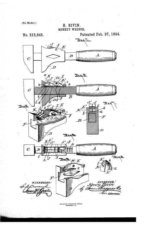
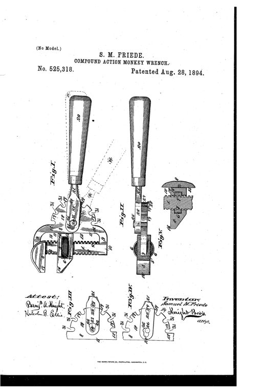
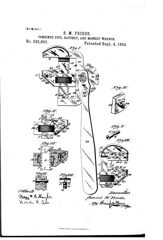
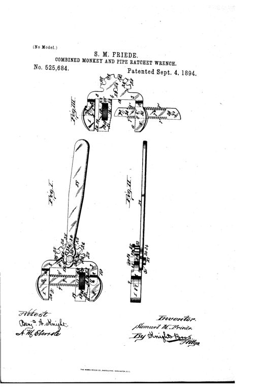
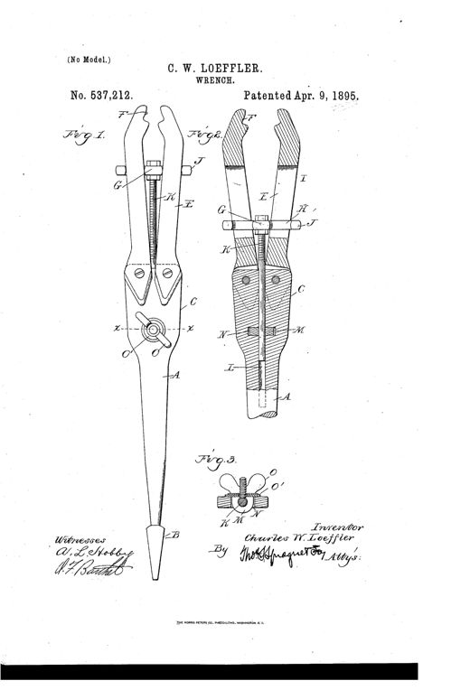
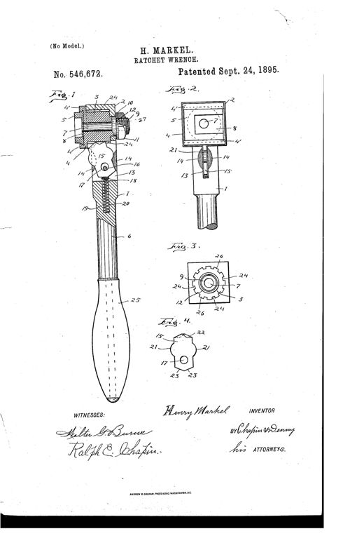
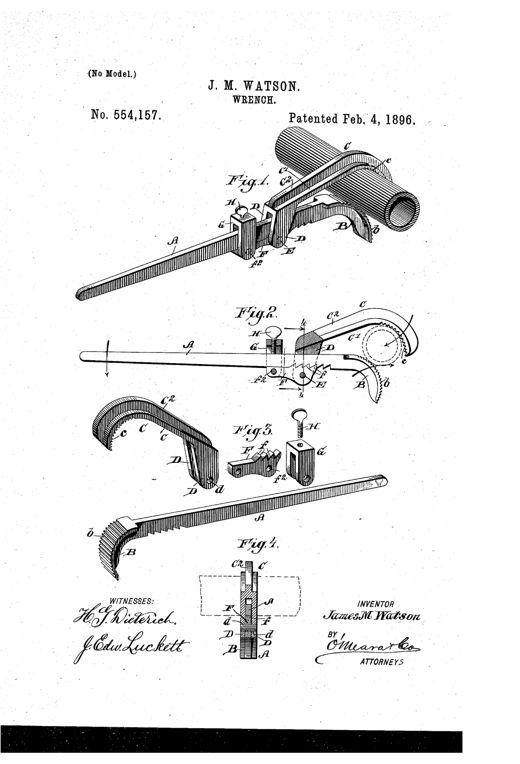
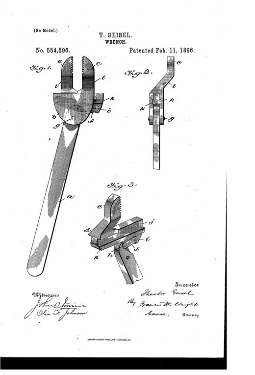
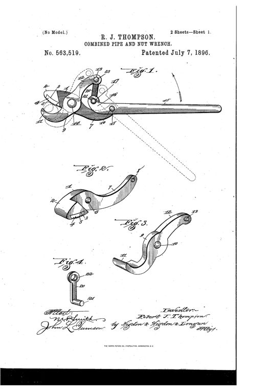
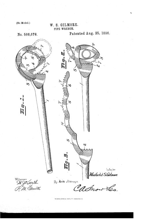
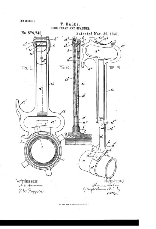
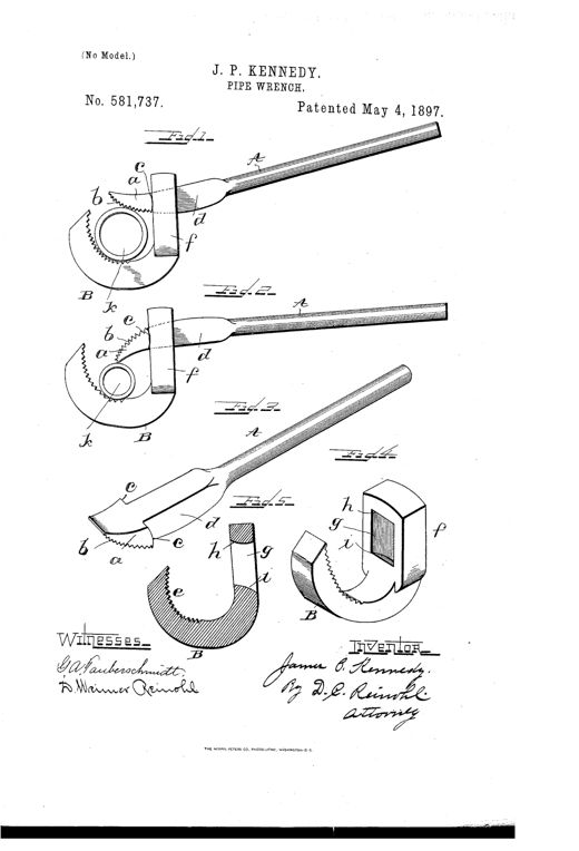
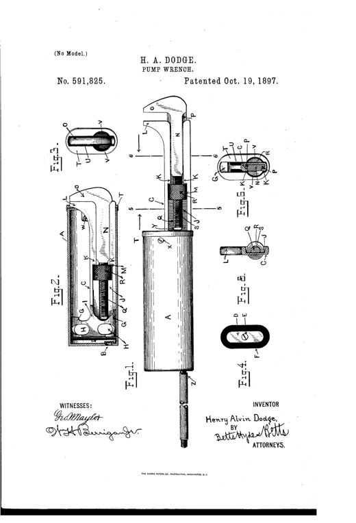
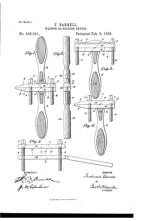
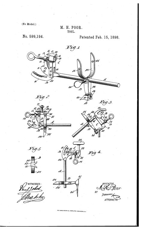
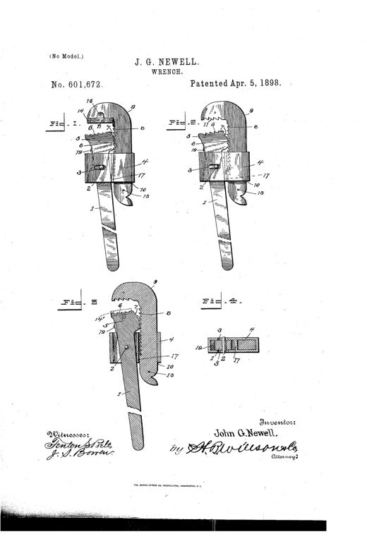
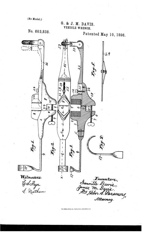
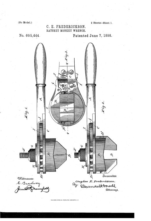
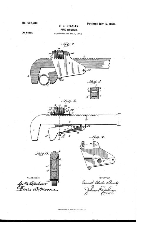
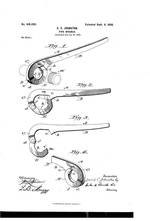
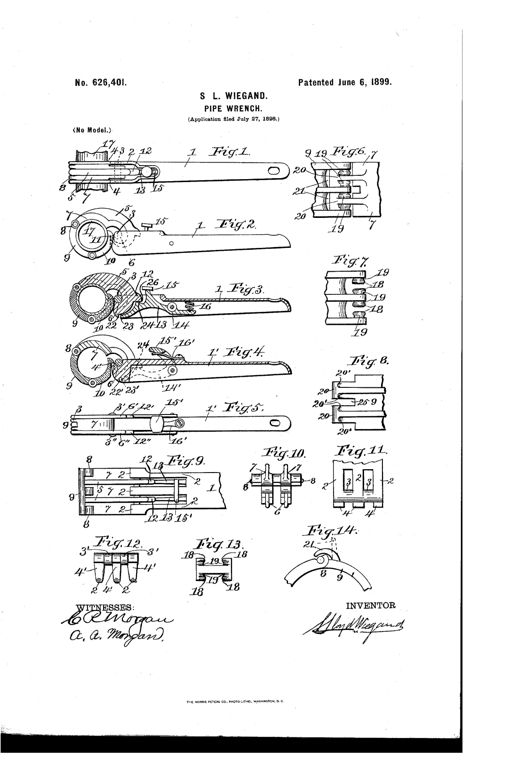
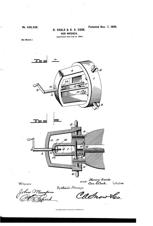
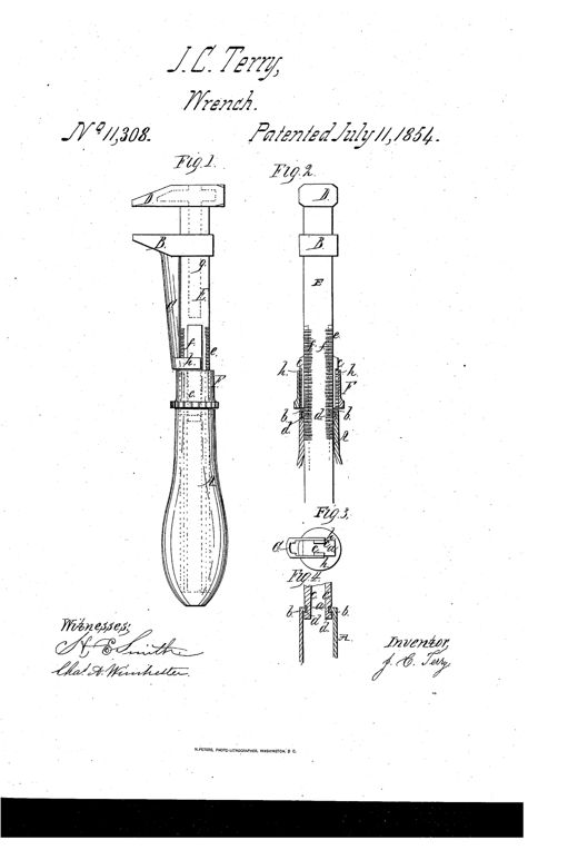
Patent drawing of a 19th-century screw wrench showing a side view with movable and stationary jaws, a threaded shank and nut, a hollow handle, and cross-sectional details of the strap attachment mechanism.SCREW-WRENCH.Jabez C. Terry · July 11, 1854Patent drawing of an 1855 screw-wrench showing a long handled tool with a fixed jaw, a sliding rack bar, a movable jaw with an eccentric shaft and thumb-piece, and cross-sections labeled a through f illustrating the screw engaging and disengaging the bar's rack.SCREW-WRENCHJoseph Hyde · October 2, 1855Two side-view patent drawings of hand wrenches, each showing a long handle, a threaded adjusting nut, a sliding jaw carriage, and a hooked claw jaw at the top, labeled Fig. 1 and Fig. 2 with lettered parts A through G.WRENCH FOR GAS-PIPE, &c.Gustavus A. Jenks · June 24, 1856Patent drawing showing a ship's windlass with chain, ratchet wheels, pump-brake heavers, and a detailed double-acting pawl with counterweight mechanism shown in multiple views.SHIP'S WINDLASSPeter H. Jackson · December 16, 1856Patent drawing of a 19th-century screw wrench showing a two-part cast construction with a sliding jaw, a threaded adjustment screw with thumb piece, a wooden handle, and several cross-sectional detail views of the jaw halves and bar.Wrench.Joseph Hyde · November 23, 1858Patent drawing of an 1860 lever-action monkey wrench showing a hammer-head handle, a movable jaw operated by a pivoted lever and curved ratchet strip, and a wooden hand-hold grip.WRENCH.F. W. Kroeber · December 18, 1860Two side-by-side patent drawings of a 19th-century pipe wrench, one showing the external assembled tool with a curved head and sliding jaw, and the other a cross-sectional cutaway revealing the internal threaded collar, spring, and pivoted handle mechanism.WRENCHCharles H. Reynolds · March 26, 1861Patent drawing of a 19th-century pipe wrench showing a long bent bar with a hinged toothed jaw, sliding collar, adjustment screw, and small detail views of the spring-loaded pin and wedge mechanism.WRENCHGeorge B. Phillips · May 28, 1861Two side-view drawings of a hand wrench with a long handle and hinged ratchet-toothed jaws, one shown closed and the other open and gripping a burr, with an arrow indicating the turning direction.IMPROVED SCREW-WRENCH.F. Hollen and A. H. Pierce · February 25, 1862Patent drawing of a monkey-style screw wrench showing the long handle, stationary and sliding jaws labeled B and B', the threaded shank A, and an exploded detail of the knurled rosette D with its grooves and projections at Fig. 2.IMPROVEMENT IN WRENCHESGeorge C. Taft · November 10, 1863Patent drawing of an 1864 pipe wrench showing a long straight lever with a hooked, toothed movable jaw hinged near the handle end, plus a detail view of the eccentric jaw with four teeth.IMPROVED PIPE-WRENCH.William Pearson · August 23, 1864Patent drawing of a 19th-century pipe wrench showing five views: two side elevations with toothed jaws and a curved pivoting claw, a rear view of the split prongs, a cross-section revealing the internal spring mechanism, and a final view of the wrench clamped onto a pipe.IMPROVED PIPE-WRENCH.James R. Brown · October 18, 1864Patent drawing of a hand wrench showing a long flattened handle ending in a toothed segment that engages a sliding jaw opposite a fixed pivoted jaw, with sectional views illustrating the jaws in open and closed positions.IMPROVEMENT IN WRENCHESWilliam Morehouse · February 27, 1866Patent drawing of a ratchet wrench showing an oval-handled top view with a round socket head containing hexagonal opening and ratchet teeth, alongside a side view of the elongated stock with a removable socket and screw catch mechanism.IMPROVEMENT IN RATCHET-WRENCHESWilliam Pirsson · May 29, 1866Patent drawing showing several views of a self-adjusting screw wrench with a wooden handle, sliding jaws, and internal pin-and-slot mechanism labeled Figures 1 through 8.IMPROVEMENT IN WRENCHESPhilip Sommer · January 29, 1867Patent drawing of a screw-wrench showing a wooden-handled bar with fixed and movable jaws, an adjusting screw with flattened side, and five small end-view cross-sections plus two longitudinal cross-sections illustrating the screw's flat and concave adjustment positions.IMPROVEMENT IN WRENCHESIsaac H. Smith · June 25, 1867Four patent drawings of pipe-tongs showing a hooked, angled jaw pivoted on an eccentric cam-head atop a long handle, illustrated gripping pipes of three different diameters and in a perspective view revealing the split, riveted jaw halves.IMPROVEMENT IN PIPE-TONGSWilliam Kenyon, Jr. · February 18, 1868Patent drawing of an 1868 wrench showing a perspective view with a fixed jaw and sliding jaw on a slotted bar, a cross-section revealing an internal cam and groove, a side view with jaws open, and two smaller modification diagrams labeled Fig. 4 and Fig. 5.IMPROVEMENT IN WRENCHESH. Schuyler Ross · March 3, 1868Two side-by-side patent drawings of a 19th-century pipe wrench showing a long bar with a curved fixed jaw B at top, a hinged serrated jaw D held by a spring, a sliding case C with screw-nut J, and a wooden handle G secured by ferrule F and nut H at the base.IMPROVEMENT IN WRENCHIra Morse · April 21, 1868Technical patent drawing showing a hand gripping a ratcheting nut wrench with a toothed wheel and adjustable jaws, alongside top, bottom, cross-section, and alternate jaw-adjustment views labeled Figs. 1 through 5.IMPROVEMENT IN WRENCHESE. J. Leyburn · October 13, 1868Patent drawing of a 19th-century adjustable monkey wrench showing the fixed jaw, tapering wedge-shaped body with a central slot, and a sliding movable jaw secured by a screw, illustrated in four figures labeled Fig. 1 through Fig. 4 with lettered parts A through H.IMPROVEMENT IN WRENCHESHoward Tilden · January 5, 1869Patent drawing of a pipe wrench showing a serrated fixed jaw, a movable jaw connected by a lever and pin through an oblique slot, and two parallel handles extending from the stem, with additional cross-sectional views of the band and pawl mechanism below.IMPROVEMENT IN COMBINED PIPE-TONGS AND WRENCHV. K. McElheny · October 12, 1869Patent drawing of a Capewell wrench showing four figures: an open handle with sliding jaw bar and coil spring (Fig. 1), a similar wrench with a fixed outer jaw and sliding inner jaw on a metal bar (Fig. 2), a cross-section through the jaw (Fig. 3), and a hammer-face end view of the second wrench pattern (Fig. 4).WRENCHGeorge J. Capewell · January 18, 1870Patent drawing of a 19th-century monkey wrench showing a solid head and corrugated stem with a sliding jaw locked by an eccentric lever, plus a cross-section of the grooved stem and jaw.IMPROVEMENT IN WRENCHESJohan Fredrik Nordquist · April 26, 1870Patent drawing showing three views of a wooden-handled adjustable wrench with a permanent upper jaw, a sliding lower jaw adjusted by a threaded stem and nut, plus detail views of the jaw's internal recess and cross-sections.IMPROVEMENT IN DUPLEX WRENCHAugustus Ball Davis · August 9, 1870Patent drawing showing a hammer-and-wrench multiple tool: Fig. 1 depicts the hammer head attached above a forked socket-wrench body with an internal socket, Fig. 2 shows the hammer mounted atop a long walking-stick handle, and Fig. 3 gives a bottom view of the wrench's square recessed jaws.IMPROVEMENT IN MULTIPLE TOOLHenry J. Harris · September 13, 1870Patent drawing of an adjustable nut wrench with a wooden handle, showing a hollow metal stem with a sliding jaw adjusted by a screw, plus cross-section details of the socket, washer, and ferrule assembly.IMPROVEMENT IN WRENCHESDaniel Campbell · October 4, 1870Line drawing of a wooden-handled combination tool showing a screwdriver shank with interchangeable points, a pivoting wrench jaw, a screw-holding clamp, and a separate pointed awl bit, labeled with reference letters A through I across seven numbered figures.IMPROVEMENT IN COMBINED TOOLS.George H. Miller · October 18, 1870Patent drawing of an 1870 adjustable wrench showing a toothed shank, sliding jaw with thumb-screw and spring catch, and a wooden handle, alongside internal cross-section views labeled Fig. 1 through Fig. 3.IMPROVEMENT IN WRENCHES.Peter Burress and Conrad Cline · November 22, 1870Line drawing of a flat steel ripping tool with an angled hook-shaped handle, a notched cutting head holding an oblique blade flanked by two prongs, shown alone (Fig. 1) and inserted between two layers of cloth in two different guide orientations (Figs. 2 and 3).IMPROVEMENT IN RIPPING-TOOLS.Justus O. Woods · August 1, 1871Two patent drawings of a hand-held pipe wrench showing a hooked jaw head with an eccentric serrated cam and claw, a square adjustable shank secured by a set-screw, and a turned wooden-style handle at the base.IMPROVEMENT IN PIPE-WRENCHESIra S. Hamilton · November 7, 1871Patent drawing showing a sectioned monkey wrench with a tapering square bar, a fixed jaw at top, a sliding jaw threaded onto a central screw, and a wooden handle secured by a ferrule block with a quill tube, alongside separate perspective views of the sliding jaw and the bare tapering bar body.IMPROVEMENT IN WRENCHES.Alonzo Whitcomb · November 7, 1871Patent drawing showing a side sectional view of a monkey wrench with wooden handle D, adjustable jaw B, threaded screw C, and shank A, plus a small cross-sectional Fig. 2 detail.IMPROVEMENT IN WRENCHES.Luke Chapman · November 21, 1871Patent drawing showing a pipe wrench with a long tapered lever handle, a curved pivoted upper jaw with serrated gripping surface, a set-screw, and a coiled spring mechanism, shown in side and edge views.IMPROVEMENT IN PIPE-WRENCHES.Henry A. Hyle · November 28, 1871Patent drawing of a combined gas-pipe wrench and vise mounted on a wooden workbench stand, showing multiple diamond-shaped toothed jaw plates, pivoted bars, a lever handle, and a separate exploded view of the adjustable bench stand with bolts.IMPROVEMENT IN PIPE-WRENCHESCharles Neames · January 9, 1872Patent drawing of a fork-wrench showing two interlocking jaws (Fig. 1) with a pivoted lever having a pear-shaped cam-head sliding within a rectangular recess, and a separate sectional view (Fig. 2) of the sliding jaw's shank and flange.IMPROVEMENT IN FORK-WRENCHES.Daniel Witt · July 16, 1872Patent drawing of a rotary wrench showing a face view (Fig. 1) with adjustable jaws, a cogged wheel, and two pawls held by a spring, and an edge view (Fig. 2) showing the wheel, neck, collar, and thumb-screw mechanism, both mounted on a long curved wooden-style handle.Improvement in Rotary-WrenchAlmon Pitcher · October 1, 1872Two patent drawings labeled A and B show a wooden-handled pipe wrench with a curved hooked jaw at top, a notched lever-bar sliding through a slot in the hook, and lettered parts f, g, z, i, h, c, d, and a marking the jaw, head, notches, pivot tooth, slot, hook, and lever-bar.IMPROVEMENT IN PIPE-WRENCHESDaniel E. Eaton · November 5, 1872Patent drawing of a railroad track wrench showing a hooked claw clamping over a rail joint, connected by a long stem with a universal joint to a socket wrench and ratchet handle.IMPROVEMENT IN COMBINED CLAMPS AND WRENCHES.Ephraim Maguire · November 26, 1872Patent drawing of an 1872 wrench showing a circular jawed head with four sliding jaws operated by an internal scroll, a hand-wheel for adjustment, and a handle with a pivoted ratcheting pawl and thimble near the shank.IMPROVEMENT IN WRENCHESOvide Bonneville · November 26, 1872Patent drawing of a wrench with a rack-toothed bar, a sliding jaw held by a spring-loaded pawl, and an adjusting screw at the base of the jaw, alongside sketches of alternate jaw and nut shapes.IMPROVEMENT IN WRENCHES.Frank Leo Delfer · November 26, 1872Patent drawing of pipe tongs showing a hook-shaped fixed jaw, a sliding jaw guided by an adjustable lever and fulcrum screw, with a detachable V-shaped cutter attachment shown in separate detail and edge views.IMPROVEMENT IN PIPE TONGS AND CUTTERS.James E. Roache · December 31, 1872Patent drawing of a self-adjusting pipe wrench showing a long handle with a curved fixed jaw and a swinging toothed movable jaw connected by a pivot and spring mechanism, shown in both elevation and cross-section views.Self-Adjusting Pipe-Wrenches.Turner Williams · February 25, 1873Two side-by-side technical drawings of a screw wrench: Fig. 1 shows the exterior profile with a rounded head and tapered handle, and Fig. 2 shows a cross-section revealing the internal shank, hollow handle, adjusting nut, and set-screw mechanism.IMPROVEMENT IN WRENCHESJames B. Weeden · March 11, 1873Patent drawing of a monkey wrench showing a toothed shank with fixed upper jaw, a sliding frame with movable jaw held by two interlocking gear wheels, a thumb-lever at the base of the frame, and a wooden handle below.IMPROVEMENT IN SCREW-WRENCHESDavid Frank · April 15, 1873Patent drawing of a curved pipe wrench with a hooked serrated dog pivoting at the jaw end, shown gripping a small pipe in Figure 1 and a large pipe in Figure 2, with a cross-section of the pivot joint in Figure 3.IMPROVEMENT IN PIPE-WRENCHESHenry B. Wheatcroft · December 2, 1873Side elevation of a monkey wrench showing the main lever A with fixed and movable jaws B, a threaded arm C locked by a half-nut D, a pivoted lever F, and a turned wooden handle G with a cam ferrule H,I at its base.IMPROVEMENT IN WRENCHESWilliam H. Crittendon · April 21, 1874Patent drawing of a wrench showing a stationary jaw A with toothed shank B, a movable jaw C engaged by a pinion b, a locking sleeve D with cam, and a stop-pawl E, alongside two cross-section views (Figs. 2 and 3) illustrating the locked and unlocked positions of the pawl and pinion mechanism.IMPROVEMENT IN WRENCHESBenjamin G. Martin · October 27, 1874Patent drawing of a crank-handled wrench with a curved handle ending in a breast-piece, a ratcheting lever mechanism with labeled pawl, ratchet, and jaws, and a small funnel-shaped oil-can mounted near the jaw assembly.IMPROVEMENT IN WRENCHESWilliam R. Moore · October 27, 1874Patent drawing of an 1875 adjustable screw wrench showing a fixed jaw C, a sliding jaw G on an angular bar B, a threaded adjustment screw with milled head M, and a wooden handle E attached via a ferrule H, with cross-sectional figures 2 through 4 illustrating the hexagonal bar profile and jaw fit.IMPROVEMENT IN WRENCHESOtis T. Bedell · January 12, 1875Patent drawing of a chain pipe wrench showing a long lever with a bent hooked end (A) engaging a circular chain of alternating double and single plate-links labeled B, C, D, and E wrapped around a pipe in Fig. 1, and a side elevation in Fig. 2 showing the stacked link construction.IMPROVEMENT IN PIPE-WRENCHES.Daniel Gilbert · February 23, 1875Patent drawing showing four figures of a 19th-century pipe wrench: a long straight handle (a) ending in a curved goose-neck jaw with a hooked head (c), a pivoted serrated tongue (d) held by an internal coil spring (g) and pin (j), shown in three cross-section views and one detached close-up of the jaw mechanism.IMPROVEMENT IN PIPE-WRENCHES.Charles H. Fulmer · March 2, 1875Two side-by-side technical drawings of a monkey wrench: Fig. 1 shows the full wrench with adjustable jaw and screw mechanism, and Fig. 2 shows a cross-section revealing an internal cam labeled 'a' with a separate locking lever labeled 'b' running down the handle.IMPROVEMENT IN WRENCHESHenry R. Sloat · April 20, 1875Patent drawing of a railroad wrench showing a ratchet handle mounted in a clamp frame with curved side bars, eccentrics, and a foot-piece hook designed to straddle a rail while tightening fish-plate nuts.Fish-Plate-Nut WrenchesJames R. Finley · July 6, 1875Patent drawing showing an S-shaped wrench with a movable jaw, adjusting screw, and a pivoted cam handle, along with several detail views of the internal cam and jaw components.IMPROVEMENT IN WRENCHESPeter Samuel · August 17, 1875A patent drawing showing a side view of a screw-wrench with a wide stationary jaw at top, a movable jaw with clasp-bearings sliding on a reinforced bar, a knurled rosette and threaded screw mechanism in the middle, a ferrule collar, and a tapered wooden handle at the bottom.SCREW-WRENCHJohn H. Coes · December 28, 1875Patent drawing of a pipe wrench showing a toothed revolving disk (B) paired with a pivoted hook-jaw (D) at the head of a long handle (A), with a rear view of the handle showing internal bolts C and E and a spring F, plus a small separate toothed insert piece G.IMPROVEMENT IN PIPE-WRENCHESEliphalet H. Adams and Asher F. Gates · January 18, 1876Two side-by-side technical drawings of a 19th-century pipe wrench, one showing the exterior elevation with a curved hook-jaw, threaded shank, sliding nut, and turned wooden handle, and the other a longitudinal cross-section revealing the internal screw threads and hatched metal components.IMPROVEMENT IN PIPE-WRENCHESIsaiah Cressey · March 7, 1876Line drawing of a slender cylindrical gun tool with a ring-shaped head (labeled D, f, g, i, B) at one end and a hexagonal socket (C) at the other, shown in perspective, section, and detached views with a modified nipple socket C' in a fourth figure.COMBINATION GUN-TOOLAlbrecht Edward Barthel · March 14, 1876Patent drawing of a 19th-century monkey wrench showing side, back, and cross-section views with labeled parts including the fixed jaw C, movable jaw D, adjusting screw E, sliding bar A, handle B, spring H, and control lever J.IMPROVEMENT IN WRENCHESEdward H. Knight · May 30, 1876Two patent drawings of a pipe wrench: Fig. 1 shows the assembled tool with a curved hook-jaw, adjustable center block, and long handle; Fig. 2 shows a cutaway cross-section revealing the internal adjusting screw and hollow shank mechanism.IMPROVEMENT IN PIPE-WRENCHESGeorge H. Crosby · June 27, 1876Patent drawing of a pipe-cutter tool showing a hooked jaw stock, sliding jaw, threaded feed-spindle, and a reversible rectangular cutting bit held in a small carrier block, illustrated in both cross-section and perspective views.PIPE-CUTTER.Hampton W. Evans · July 4, 1876Elongated multi-tool with a screwdriver tip, hammer head, and pyramid ice-pick at one end, a forked tack-puller at the other, ruler markings along the shaft, and a curved poker/pot-lifter finger and small sharpening plates along its length.IMPROVEMENT IN COMBINED IMPLEMENTSLester Beach · August 1, 1876Patent drawing of a hinged pipe wrench with a long slotted lever, two toothed curved gripes labeled B and C, a sliding shoulder S, and a hinge joint H, shown both open (Fig. 1) and closed around a pipe P (Fig. 2).IMPROVEMENT IN PIPE-WRENCHESDaniel Barnard Cook · December 5, 1876Patent drawing of a pipe wrench showing a long handle A with a hooked jaw E at the top pivoted in a casing C, a sliding straight jaw F with knurled ridges, an adjusting screw rod G with a round thumb-piece G' below, and a separate detail view (Fig. 2) of the casing bracket with recesses c c.IMPROVEMENT IN PIPE-WRENCHESCharles Peterson and Anton Dunnebake · January 2, 1877Patent drawing of a screw wrench showing the full side view with adjustable jaws and rosette screw, plus cross-sectional details of the cast metal handle with internal nut and shank.IMPROVEMENT IN WRENCHESLoring Coes · January 9, 1877Patent drawing of a 19th-century monkey wrench showing side, front, and back views with labeled jaws, threaded stem, and adjusting nut, along with several small cross-section diagrams of the jaw and flange design.IMPROVEMENT IN MONKEY-WRENCHES.Jay W. Powers · February 27, 1877Patent drawing showing a spoked wheel with a lever-clamp device gripping its axle, plus a detailed perspective view of the curved, roughened clamp jaw mechanism below.IMPROVEMENT IN LEVER-CLAMPSVan Court Yantis · March 20, 1877Patent drawing of a hollow-handled wrench shown in vertical cross-section, with threaded jaw shanks visible inside, plus two small circular cross-section diagrams labeled Fig. 2 and Fig. 3 showing the oblong and round threaded shank profiles.WRENCHJames Shepard · March 27, 1877Patent drawing showing a pipe wrench lever with a toothed end, several interchangeable curved toothed hooks, a spring ratchet-catch mechanism, and two views of the lever and hook assembled in open and closed positions.IMPROVEMENT IN PIPE-WRENCHES.Eliezer Rees Mathews · April 17, 1877Two side-by-side line drawings of an adjustable monkey wrench: Fig. 1 shows the exterior with a fixed jaw B, sliding toothed jaw D, ratcheted bar A, thumb-piece c, and turned wooden handle C; Fig. 2 is a cutaway section revealing the internal spiral spring f seated in a socket e behind the sliding jaw, with a small access hole d.IMPROVEMENT IN WRENCHESSamuel Christoffer Englund · May 29, 1877Patent drawing showing an adjustable monkey wrench with a long curved handle, a fixed and movable jaw in the head, and separate detail views of the sliding jaw and threaded adjusting screw with labeled parts A through K.IMPROVEMENT IN WRENCHESAndrew B. Lipsey · July 31, 1877Patent drawing of a pipe-tong wrench showing a curved hooked link, a long lever handle with a threaded shank, and a knurled adjusting screw with a ball-shaped knob used to set the pinching point against a pipe.IMPROVEMENT IN PIPE-TONGSWilliam Lomas · August 14, 1877Patent drawing of a pipe wrench showing a long wooden handle attached to a shank with a fixed toothed jaw and an adjustable sliding bar bearing a spring-mounted wedge-shaped jaw, with a cutaway section revealing the internal ratchet and spring mechanism.IMPROVEMENT IN PIPE TONGS OR WRENCHES.Edward B. O'Kelly · August 28, 1877Patent drawing of a monkey wrench showing a fixed jaw at top, a sliding movable jaw with an internal locking screw and thumb-piece, a cross-section of the bar's mutilated threads, and a tapered wooden handle below, with hand-lettered part labels A through h.IMPROVEMENT IN MONKEY-WRENCHESAlbert A. Sanborn and Charles Burroughs · September 11, 1877Patent drawing showing four figures of a 19th-century combination wrench and pipe cutter, including full side views with wooden handles, a top view of the jaw mechanism, and a small detached rotary cutting disk on a shaft.IMPROVEMENT IN COMBINED WRENCH AND PIPE-CUTTERBernard Donohue · September 25, 1877Patent drawing of a 19th-century monkey wrench showing a perspective view with labeled jaws, sliding stem, threaded nut, and handle ferrule, along with a longitudinal cross-section and two transverse sections illustrating the locking nut mechanism.IMPROVEMENT IN WRENCHESCalvin H. Covell · November 20, 1877Patent drawing of a combined wrench and vise showing a ratcheting head with two clamping jaws atop a long ruled handle, with a cross-sectional detail of the internal bolt, spring, and bridge mechanism.Combined Wrench and Vise.Homer Tompson Gates · December 18, 1877Patent drawing of an adjustable watch key showing a tubular shank with a stem handle at one end and expandable gripping jaws driven by internal gearing at the other, with cross-section and end views illustrating the mechanism.Adjustable Watch-Key.William Haines · April 16, 1878Patent drawing of a pipe wrench showing a hooked stationary jaw with inward-pointing teeth, a movable toothed jaw sliding on a threaded shank through a slotted frame, an egg-shaped adjusting nut, and a long tapered wooden handle, with a separate cross-section view labeled Fig. 2 showing the nut and slot arrangement.IMPROVEMENT IN PIPE-WRENCHESLawrence Glynn · May 7, 1878Patent drawing of a wrench with a circular handle end holding a removable pentagonal-cogged nut-holder, shown in front elevation, exploded nut-holder view, and rear elevation with internal spring and catch mechanism.IMPROVEMENT IN WRENCHESGurdon S. Goodspeed · May 7, 1878Patent drawing of a 19th-century pipe wrench showing a long serrated lever A with a hinged jaw B connected by a bent yoke C and pivot D, plus a small removable slide E that wedges between the lever and jaw to lock the grip; separate figures show the lever edge-on, the jaw-and-yoke assembly, and the slide piece in isometric detail.Pipe-Wrench.John Hartman, Jr. · June 18, 1878Patent drawing of a combined pipe-wrench and pipe-cutter tool showing a curved hooked head with a rotary cutter and pivoting dog, a threaded shaft body, and a long handle ending in an oval knob, with a separate enlarged detail of the adjustable chamfering screw and swivel joint.IMPROVEMENT IN PIPE-WRENCHES WITH CUTTERS.John Brewer · August 20, 1878Patent drawing of an adjustable wrench with a long handle, showing an internal pinion gear meshing with a toothed rack on one jaw, and a spring-loaded pawl block visible in cross-section, with dashed lines indicating the jaws swung to alternate positions.IMPROVEMENT IN WRENCHESHenry W. Brett · September 3, 1878Patent drawing of a 19th-century monkey wrench showing a handle with a fixed jaw, a sliding movable jaw, and a curved cam lever used to lock the jaw in place, with additional cross-section details of the jaw slot and grooves.IMPROVEMENT IN WRENCHESJohn M. Marty · September 10, 1878Patent drawing showing two interchangeable attachments for a handle: Fig. 1 depicts a curved cutting blade with a hooked jaw and adjusting thumb-screw, and Fig. 2 depicts a serrated wrench jaw with a similar curved handle and slot for the pivot bolt.IMPROVEMENT IN PIPE-WRENCHES WITH CUTTERS.William L. Truland · September 24, 1878Patent drawing of a combination nut and tap wrench showing a tapered shank with two side arms holding opposing jaws adjusted by right-and-left-hand screws with milled and T-shaped heads, alongside a front and end view of the same mechanism.IMPROVEMENT IN NUT AND TAP WRENCHESJoseph Goodrich · December 10, 1878Patent drawing of a hand-held pipe wrench with a wooden handle, threaded shank, adjusting nut, and a jawed head containing two toothed dogs and a cutter blade for gripping and cutting pipe.IMPROVEMENT IN PIPE-WRENCHES WITH CUTTERS.Benjamin Franklin and James Gilberds · February 18, 1879Patent drawing of a pipe wrench showing a handled shank ending in a toothed circular disk jaw, with a two-part hooked movable jaw pivoted eccentrically to grip a section of pipe, shown in side and edge views.IMPROVEMENT IN PIPE-WRENCHESSamuel W. Hudson · February 18, 1879Patent drawing of an L.S. Starrett wrench showing a longitudinal cross-section with labeled jaw, screw, spring, and brace parts, plus a side view and detail cross-sections of the jaw and pivoting brace mechanism.IMPROVEMENT IN WRENCHESLaroy S. Starrett · February 25, 1879Patent drawing of a 19th-century pipe and nut wrench showing two figures: an upper jaw with a wing-nut secured bit and a lower sliding concave block adjusted by a screw, gripping a pipe section labeled P and nut N.IMPROVEMENT IN PIPE AND NUT WRENCHESDaniel Fisher · March 4, 1879Patent drawing of a bung-bush insertion wrench showing a rounded head with a crossbar handle, a conical screw-threaded stem, four expanding corrugated plates arranged around the stem, and a retaining cap secured by a nut at the base, shown in elevation, cross-section, and end views.IMPROVEMENT IN WRENCHES FOR INSERTING BUNG-BUSHESDavid Ackerman · March 11, 1879A patent drawing of a two-handed carriage-wheel wrench with a central handle, two pairs of hinged clamping jaws forming an X-shaped body, and threaded clamping screws with knurled thumb wheels on each side.IMPROVEMENT IN CARRIAGE-WHEEL WRENCHES.Nelson R. Pratt · May 20, 1879Patent drawing of a bit-stock wrench showing a conical shank with pivoted expanding jaws, a threaded funnel-shaped sleeve, and a ratchet-equipped variant attached to a brace handle.IMPROVEMENT IN BIT-STOCK WRENCHES.Quimby S. Backus · June 24, 1879Patent drawing of a monkey wrench with a stationary jaw B and sliding jaw C on a threaded shank, alongside interchangeable attachments including a pipe-threading die, bolt-threading die box, pipe cutter, and nut tap, each fitted with an arm L to insert into a socket on the sliding jaw.IMPROVEMENT IN MONKEY-WRENCHESBaziel Winans Lloyd · July 22, 1879Patent drawing showing four views of hinged pipe tongs with triangular jaws, a sliding yoke, and long handles used to grip and turn oil-well tubing.IMPROVEMENT IN TUBING-TONGSLemuel W. Young · September 2, 1879Patent drawing of a pipe wrench showing a curved fixed jaw M at one end of a long bar A, with a sliding frame C, screw cylinder E, movable jaw B, and a curved cam-lever handle D pivoted at F, illustrated in side elevation, cross-section, and jaw detail views.IMPROVEMENT IN PIPE-WRENCHESDan P. Foster · December 9, 1879Patent drawing of an adjustable wrench with a toothed alligator-style jaw at the top, a long bar with a sliding sleeve, and a pair of curved jointed spring levers forming a handle that closes the jaw when squeezed, shown in side and top views alongside cross-section details of the joint and threaded adjusting nut.IMPROVEMENT IN ADJUSTABLE WRENCHES.Seth E. Hurlbut · December 23, 1879Patent drawing of a hand vise and wrench tool showing two long jaws (A and A') joined by a threaded bar and thumb-nut, connected below to a cylindrical wooden-handled body with an internal screw-bolt and spring mechanism, alongside detail views of the jaw tip, nut flange, and handle cross-section.HAND-VISE AND WRENCHCharles E. Bailey · December 5, 1882Two side-by-side patent drawings of a combined pipe-tongs and wrench tool, each showing a hooked frame labeled A and B with an internal toothed sliding bar H and pivoted lever F, one figure depicting the tongs configuration and the other a cross-section showing the wrench configuration with hatched internal parts.COMBINED PIPE-TONGS AND WRENCHElbridge F. Barnes · July 31, 1883Patent drawing showing a long-handled wrench with a sliding jaw bar containing internal spring-loaded roller chambers, shown in assembled and open views with detail insets of the roller and cover plate.AUTOMATIC SELF-SETTING WRENCHBenjamin F. Bennett · November 6, 1883Patent drawing of a wrench with a sliding toothed jaw on a main bar, a hinged lever handle connected by pivoted fulcrum braces, and a small locking loop clasp, shown in four figures.SELF-ADJUSTING FULCRUM-LEVER WRENCHBenjamin F. Bennett · April 15, 1884Patent drawing of a ratchet wrench showing five figures: a perspective view of the assembled tool with adjustable jaws and knurled screw, two cross-sectional views revealing internal pawls and ratchet teeth, a small circular cross-section, and an enlarged perspective of the head with parts broken away to show the sliding jaw mechanism.WRENCH.Ernest Frederick Rettberg and Charles Carroll Ellis · February 2, 1886Patent drawing of a pipe wrench showing a long tapered handle bar with a serrated head, a hinged slotted jaw piece, and a wire spring looping around studs to hold the jaws closed.PIPE-WRENCHGeorge M. Gillett · March 30, 1886Patent drawing of a wrench with an elongated tapered handle ending in a screwdriver tip at top and a curved gripping jaw with ratchet teeth at bottom, with two detailed close-up views (Fig. 1 and Fig. 2) showing the pivoting jaw, coiled spring, set-screw, and locking lug mechanism.WRENCHAlbert Langstrom · June 1, 1886Patent drawing of a flat wrench with multiple hexagonal openings of different sizes, a detachable double-bladed screwdriver clamped to one end by a set screw and plate, shown in two side views, applied to a bicycle spoke, and in cross-section.COMBINATION-TOOLReinhard T. Torkelson · October 16, 1888Patent drawing of a monkey wrench showing a sectional view of the sliding threaded jaw mechanism with a pivoting handle, pawl, and notched locking teeth, along with cross-sectional and perspective detail views labeled Figs. 1 through 5.WRENCH.Vincent J. McDonnell · April 30, 1889Patent drawing of a monkey-wrench-style tool showing an angled handle with a sliding jawed head, a thumb-nut adjustment collar, and a retractable screwdriver blade housed within the handle, with four labeled figures illustrating the assembled tool, cross-sections, and the screwdriver detail.COMBINED WRENCH AND SCREW-DRIVER.Burr Albert Haines · September 17, 1889Patent drawing of a pipe wrench showing two toothed jaws (A and B) joined by a threaded lever (C) passing through flaring slots, secured by a convex nut (E), with a spring (F) shown between the jaws and a separate detail view of the nut in Fig. 2.PIPE-WRENCH.Andrew J. Curtis · April 8, 1890Patent drawing showing a curved two-piece hub wrench with pivot bolt, jaws gripping an axle nut, and knurled binding screws on the outer ends, along with detail perspectives of the individual members.HUB-WRENCH.Melville Beach · July 8, 1890Patent drawing of a 19th-century combination wrench showing a sliding jaw, toothed rack-bar, pivoted lever handle, screwdriver tip, and a detachable U-shaped pipe-wrench casing, with detail views of the jaw mechanism and wire-cutter.COMBINED NUT-WRENCH AND TOOLWilliam Henry Huston · October 21, 1890Patent drawing of a monkey wrench with a long handle, a screw-threaded bar, a sliding sleeve with thumb-nut, and two divergent toothed jaws connected by links, shown in both side and edge views.MONKEY-WRENCH.William W. Charlton · November 4, 1890Patent drawing showing three views of a combination hand tool with a crank handle, a slotted stock containing a sliding plunger, and pivoted jaws at the tip that can be adapted to grip a nut, a bit shank, or a screw-driving blade.WRENCH.Fred E. Putnam · December 2, 1890Patent drawing of a pipe wrench showing a twisted handle forming two arms, a stationary jaw at top with a screw-thread adjustment nut, and a sliding box holding a reversible toothed pawl on a pivot pin, with separate detail views of the pawl and slide components.WRENCHFrank S. Cook · March 3, 1891Patent drawing of a wrench showing a long handle with a sliding, bolt-locked head bearing a pivoted hook-shaped serrated jaw opposite a fixed angular serrated jaw, with a separate cross-sectional detail of the head assembly.WRENCHBenjamin Blanton Farris · March 10, 1891Patent drawing of an 1891 ratchet wrench showing a bulbous wooden handle, a bifurcated ratchet handle with pawl, a cylindrical shank, and adjustable sliding jaws with a milled nut for tightening, alongside a detail view of the pawl rod assembly.WRENCH.Charles H. Driver · April 7, 1891Patent drawing of a long-shanked adjustable wrench with a fixed jaw at top, a sliding movable jaw with an embedded spring pawl, a threaded bolt running down the shank into a rotating nut inside a pivoted hollow handle, and detail insets of the jaw, stay-block, and internal nut.WRENCH.Frank Stacey Chaney · April 28, 1891Patent drawing of a nested multi-blade combination wrench, showing folded and exploded views with lettered parts labeled A, B, a, b, l, o, s, and h.COMBINATION-WRENCHWilliam W. Shoe · May 9, 1893Patent drawing of a monkey wrench showing the handle, notched shank, sliding jaw with internal pawl and spring mechanism, and a hammer-shaped rigid head, with multiple cutaway and detail views labeled with reference letters A through L.MONKEY-WRENCH.Henry Bivin · February 27, 1894Patent drawing of a compound-action monkey wrench showing the wrench body with adjustable jaw and screw stem, a long handle with a locking commander head, a semi-circular toothed rag-spur gear plate, and detail views of the ratcheting frame and key-pin engagement.COMPOUND-ACTION MONKEY-WRENCH.Samuel M. Friede · August 28, 1894Patent drawing of a combined pipe, ratchet, and monkey wrench showing a long flattened screw-stem handle with an adjustable jaw mechanism at top, a curved bail-shaped frame with cog-spur gear plate, a pivoting lever handle with an inverted T-slot, and several detail insets of the detachable ratchet plates, lock bolts, and jaw components.COMBINED PIPE, RATCHET, AND MONKEY WRENCH.Samuel M. Friede · September 4, 1894Patent drawing showing three views of a combined monkey and pipe ratchet wrench: a side view with a long handle and geared head, a slim edge view of the handle, and a modified version with integral jaws and a spur-gear plate.COMBINED MONKEY AND PIPE RATCHET WRENCH.Samuel M. Friede · September 4, 1894Patent drawing of an adjustable wrench with a long shank, squared bit end, pivoted spreading jaws at the top, and a threaded rod with wing nut for locking the jaw spread, shown in side view, cross-section, and end view.WRENCH.Charles W. Loeffler · April 9, 1895Patent drawing of a ratchet wrench showing a sectioned side view with internal ratchet, pawl, spring, and wooden handle, plus front and rear detail views of the ratchet head and pawl.RATCHET-WRENCH.Henry Markel · September 24, 1895Patent drawing of an adjustable pipe wrench showing a long handle with a fixed serrated jaw and a curved swinging upper jaw locked by a toothed pawl and set-screw clip, with detail views of the pawl, ears, and cross-section of the jaw assembly.WRENCH.James M. Watson · February 4, 1896Patent drawing showing a long-handled wrench with a sliding jaw mechanism, an offset toothed jaw head, and a detailed perspective view of the internal link and pivot parts.WRENCH.Theodor Geisel · February 11, 1896Patent drawing of a combined pipe and nut wrench showing two hinged jaws, one smooth curved and one with a corrugated removable face-plate, connected via a pivoted link and toggle mechanism to a long handle, with numbered reference lines pointing to each part.COMBINED PIPE AND NUT WRENCH.Robert James Thompson · July 7, 1896Patent drawing of a chain-link pipe wrench showing a long handle with a toothed head and a folding chain of curved ratcheting links used to clamp around a pipe of varying diameter.PIPE-WRENCH.Winfield S. Gilmore · August 25, 1896Patent drawing showing three views of a fireman's combined hose-strap and spanner tool: a side elevation with a hooked spanner head and folded strap (Fig. 1), a cross-sectional detail of the shank and strap (Fig. 2), and a perspective view of the tool used to suspend a length of hose via a looped strap (Fig. 3).HOSE-STRAP AND SPANNER.Thomas Haley · March 30, 1897Patent drawing showing a pipe wrench with a long straight lever ending in a serrated jaw, paired with a curved sliding jaw featuring a slotted shank, shown in five views including side elevations, detached perspectives, and a cross-section.PIPE-WRENCH.James P. Kennedy · May 4, 1897Patent drawing of a Henry Alvin Dodge pump-wrench showing a hollow elliptical pump body (A) with a sliding wrench-stem (C) bearing a fixed jaw (L) and a movable jaw (O) on a shank (N), plus cross-sectional and top views revealing the internal plunger, ribs (K), finger-piece (R), and guide braces (G).PUMP-WRENCH.Henry Alvin Dodge · October 19, 1897Patent drawing showing five views of a double-jawed adjustable wrench with knurled screw shanks, polygonal screw heads, and oval handles, used for gripping tools or clamping work on a drill-press table.WRENCH OR HOLDING DEVICE.Ferdinand Barrell · February 8, 1898Line drawing of a multi-part patent tool showing a round body-bar with a pipe-wrench jaw at one end, two adjustable pivoting arms with vise-jaws, points, and split jaws, and a separate handle with a boring bit, across five labeled figures.TOOL.Morrill Hart Poor · February 15, 1898Patent drawing of a hand wrench with a rectangular handle, a slotted yoke, ratchet-toothed fixed and movable jaws, and a small pivoting auxiliary smooth jaw, shown in four labeled figures with numbered reference lines.WRENCHJohn G. Newell · April 5, 1898Patent drawing of a vehicle wrench with two hinged jaw arms, an adjustable sliding jaw held by a thumb-screw, and a curved spring hook designed to catch a wheel spoke, shown in side, top, and sectional views alongside an illustration of the wrench clamped onto a wagon wheel.VEHICLE-WRENCH.Granville Davis and James M. Davis · May 10, 1898Patent drawing of a ratchet monkey wrench showing the long handle, a rotatable jawed head with sliding jaws, an internal ratchet ring, and detail views of the linkage bolt and dog mechanism.RATCHET MONKEY-WRENCHClayton E. Frederickson · June 7, 1898Patent drawing of a pipe wrench with a long toothed handle bar, a sliding two-part box, and a swinging trunnion-mounted grip jaw gripping a pipe, with additional cross-section and detail views of the box and jaw parts.PIPE-WRENCHOramel Charles Stanley · July 12, 1898Patent drawing of a pipe wrench with a long curved handle, a fixed hook-shaped jaw at the lower end, and a pivoting outer jaw with teeth that closes around a pipe, shown in four figures illustrating open and closed positions.PIPE-WRENCH.David C. Johnston · September 6, 1898Patent drawing showing a pipe wrench with a hollow trough handle and a hinged ring of curved segments that close around a pipe, with detail insets of hooks, pivots, ridged joints, and a spring-loaded locking lever.PIPE-WRENCHS Lloyd Wiegand · June 6, 1899Patent drawing of a cylindrical hub-wrench band with a yoke brace, crank handle, and spring-metal clamping jaws, shown in perspective and in cross-section fitted over a wheel hub.HUB-WRENCHHenry Sauls and George S. Cook · November 7, 1899