IMPROVEMENT IN WRENCHES
A Worcester rival fixes the monkey wrench's weak spot: the cracking ferrule
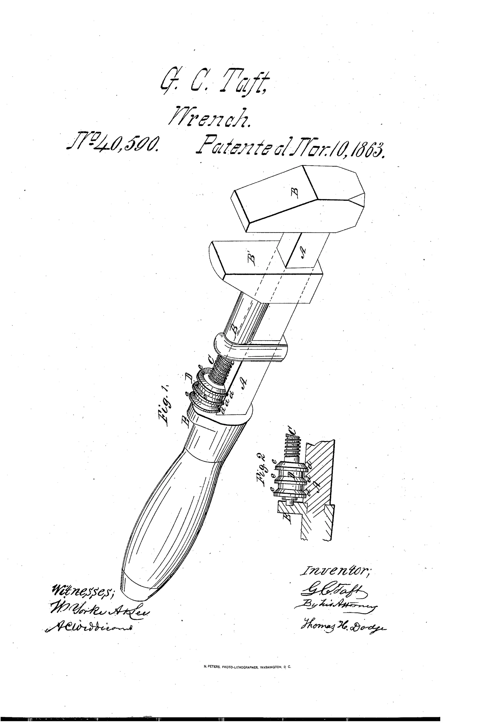
A self-adjusting rosette screw wrench
⚙ How it works
The wrench has a shank A with a stationary jaw B and a sliding jaw B' whose part B'' carries the operating screw C. A rosette D, formed in one piece with the screw C, is journaled to a ferrule E and has beveled projections e e e that ride in parallel grooves d d d cut into the shank. Turning the rosette right or left advances or retracts the sliding jaw to fit the object being clasped. Because the grooves and projections run at right angles to the jaw's motion rather than spirally, the ferrule is relieved of strain that would otherwise crack or displace it.
⚙ What was claimed
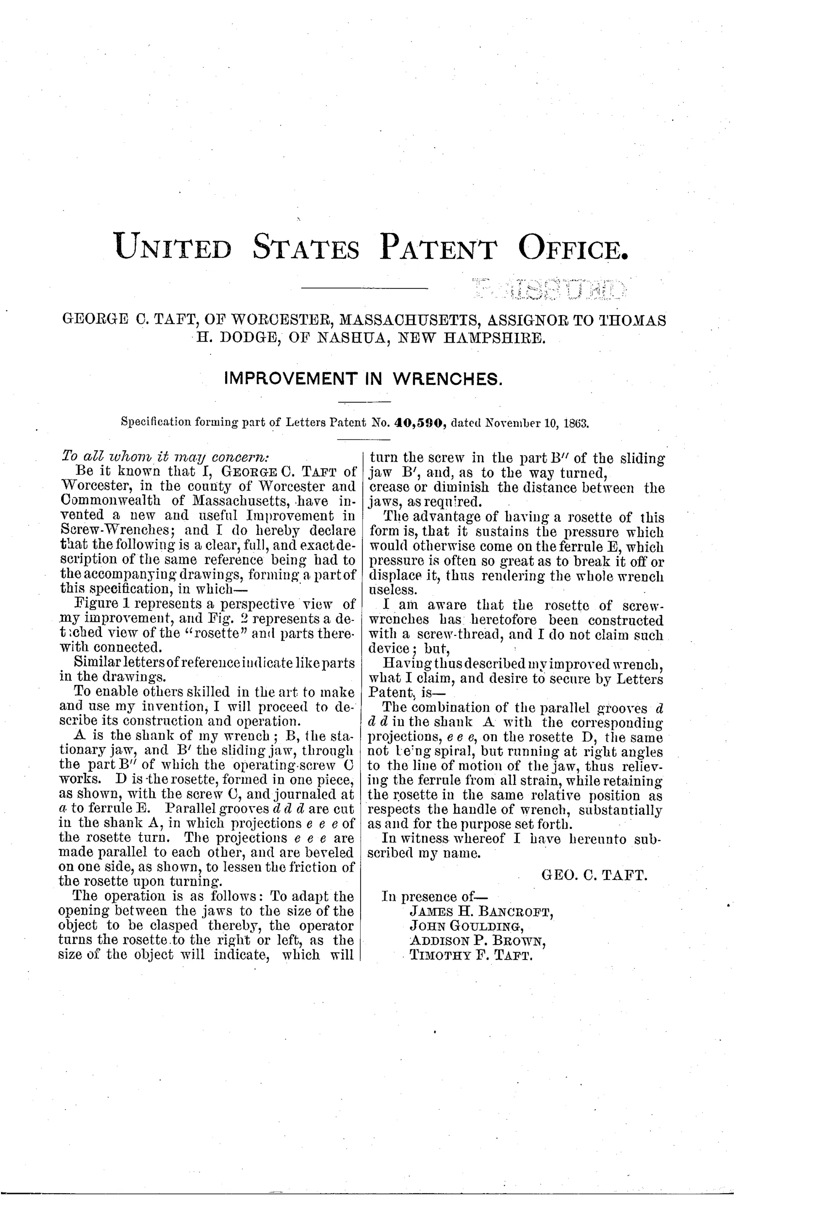
“The combination of the parallel grooves d d d in the shank A with the corresponding projections, e e e, on the rosette D, the same not being spiral, but running at right angles to the line of motion of the jaw, thus relieving the ferrule from all strain, while retaining the rosette in the same relative position as respects the handle of wrench, substantially as and for the purpose set forth.”
In plain English: The wrench uses straight (non-spiral) grooves in the shank matched with projections on the rosette, set crosswise to the jaw's movement, so the ferrule never bears the adjusting strain while the rosette stays fixed relative to the handle.
⚙ In the inventor’s words
“The advantage of having a rosette of this form is, that it sustains the pressure which would otherwise come on the ferrule E, which pressure is often so great as to break it off or displace it, thus rendering the whole wrench useless.”— George C. Taft, from the specification
Manufactured and sold
Taft was an established Worcester wrench maker and marked Taft screw wrenches survive, so this ferrule-relieving construction plausibly entered his production line; a specimen matched to the drawing would confirm the specifics.
⚙ Commentary
By 1863 the Coes-pattern screw wrench had been the Worcester standard for two decades, and everyone who used one hard knew its failure mode: the thin ferrule that holds the rosette to the handle takes the adjusting thrust, and eventually it splits or shifts and the whole tool is scrap. Taft's patent goes straight at that. His rosette carries beveled projections that ride in grooves cut into the shank itself — and the whole point of the claim is that those grooves are straight, running square across the jaw's line of travel, not spiral. The rosette turns in place, the projections bear against solid shank metal, and the ferrule is reduced to a keeper instead of a thrust bearing.
Look at Fig. 2, the exploded detail, and you can see the geometry: the screw and rosette are one piece, the ring of projections e sits in the crosswise grooves d, and the load path bypasses the ferrule E entirely. It is not a new adjustment mechanism — the wrench works exactly like every other screw wrench — it is a durability fix, which is a humbler and often more commercially useful kind of invention.
Taft was no outsider tinkering: he was a Worcester wrench man in the town that owned this trade, and this reads like a shop-floor answer to a warranty problem. It sits in the story as refinement, not revolution — the kind of quiet improvement that decided which maker's wrenches were still in the toolbox twenty years on. DATAMP documents the patent.
Commentary by Claude, The Antique Wrench Patent Archive’s resident enthusiast