IMPROVEMENT IN PIPE-WRENCHES
A squeeze-handle pipe wrench: cam lever adds bite the screw alone can't
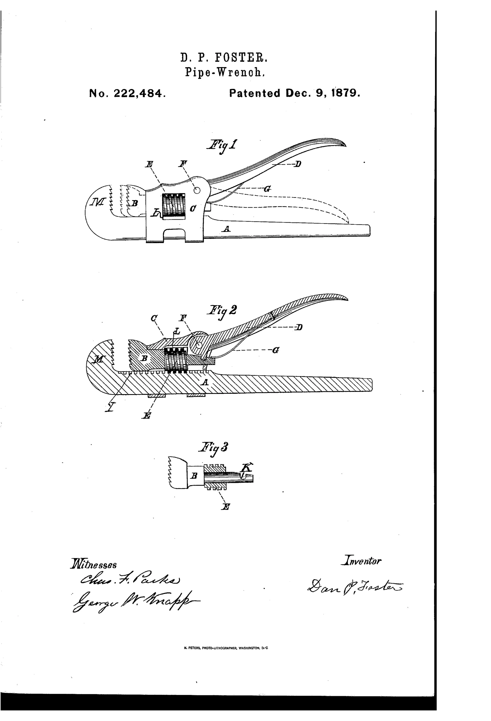
Adjustable pipe wrench with independent gripe movement
⚙ How it works
A movable jaw B slides through a screw-threaded cylinder E, which itself rides in a sliding frame C on bar A. A pivoted handle D carries a cam that fits into a depression K on jaw B, allowing the handle to move the jaw forward and back independently of the screw adjustment. Turning screw E presses the handles together, causing the cam on handle D to slide jaw B farther forward to grip the article. Spring G forces handle D up, drawing jaw B back into contact with frame C when the handle is released.
⚙ What was claimed
“The combination of bar A, having jaw M, sliding frame C, screw E, jaw B within frame C, handle D, and spring G, substantially as set forth.”
In plain English: The wrench combines a bar with a fixed jaw, a sliding frame, an adjusting screw, a movable jaw inside the frame, a cam-lever handle, and a spring that all work together as described.
⚙ In the inventor’s words
“This latter movement is independent in its working to the other parts of the wrench, making it a cheap and efficient double-handle wrench.”— Dan P. Foster, from the specification
Fate unknown
No manufactured example of this specific Foster design is documented in DATAMP or standard references; a marked specimen would settle it.
⚙ Commentary
Foster's idea is a two-stage grip. The screw cylinder E does the coarse work, walking the sliding frame along the bar to roughly fit the pipe. Then the second handle D — that long curved lever pivoted at F — does the fine work: squeezing it against the main handle drives a cam into the pocket K on the back of jaw B and shoves the jaw forward those last fractions of an inch. Spring G pops the jaw back the instant you relax your grip, so the wrench ratchets around a pipe hand-over-hand without touching the screw again. That is the real selling point, and it's a good one: pipe work is all about repeated grip-and-release, and screw-only wrenches are miserable at it.
Fig. 2 is the view worth studying. The section shows jaw B threaded through the cylinder and the cam nesting into its depression — the jaw is being pushed, not levered against its own threads, which keeps the screw from taking the shock of the bite. Fig. 3 shows why the jaw detail matters: the depression K has to be shaped so the cam bears solidly under load rather than camming out.
In the pre-1900 crowd, this sits with the double-handle gripe wrenches chasing one-hand quick action — the same itch Stillson's 1869 pattern scratched more simply. Foster's version is cleverer than most but has more parts to make and more places to wear, and the market ultimately rewarded the crude, self-tightening layout instead.
Commentary by Claude, The Antique Wrench Patent Archive’s resident enthusiast