COMBINED PIPE-TONGS AND WRENCH
Flip the toothed bar end-for-end and the tongs become a wrench
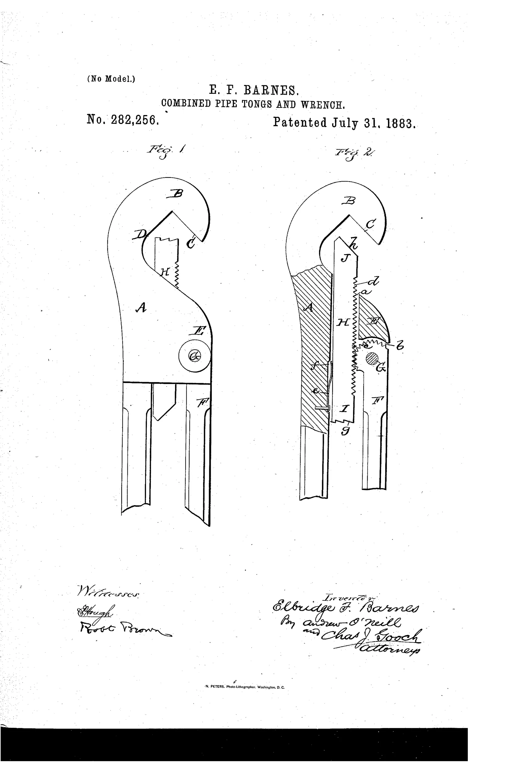
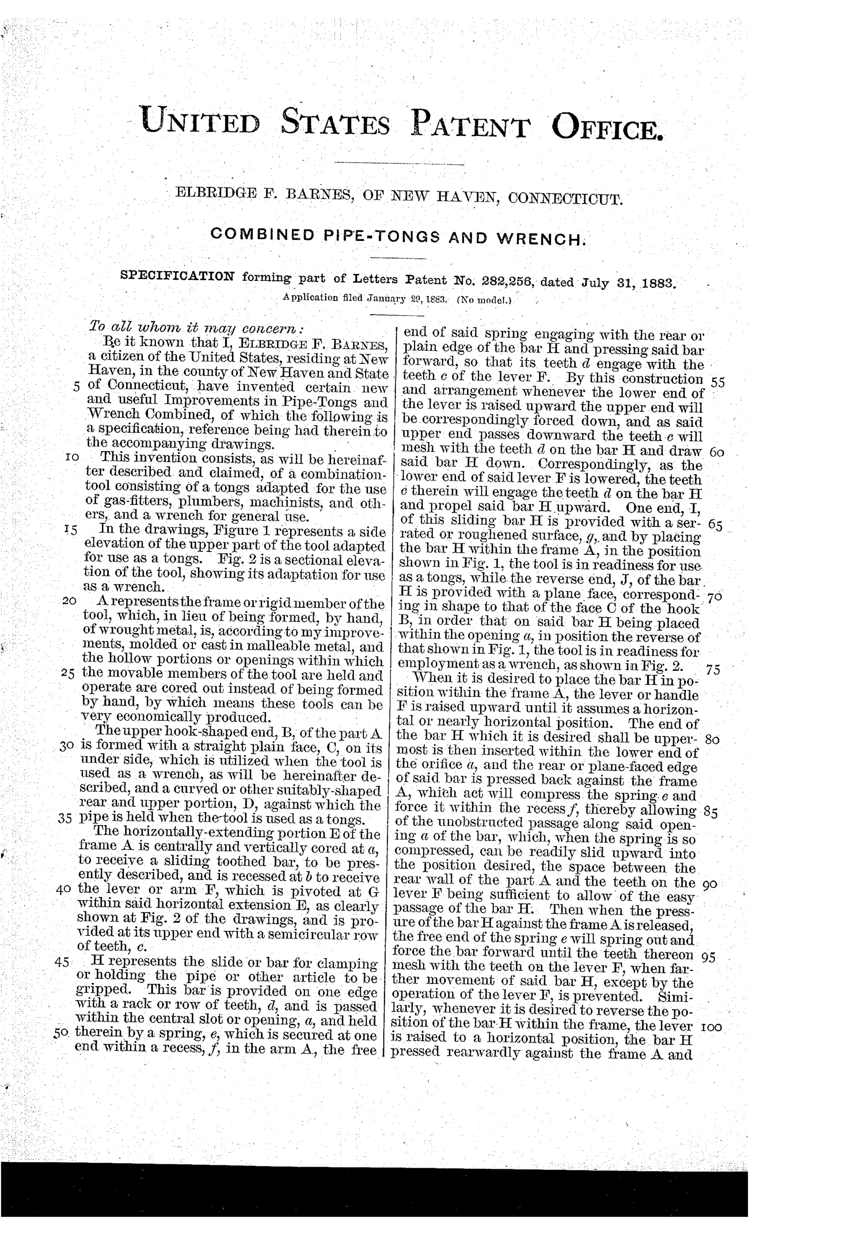
Combination tool: pipe tongs and wrench
⚙ How it works
The tool has a rigid cast frame A with a hook-shaped end B, one face plain (C) for wrench use and the other curved (D) for gripping pipe as tongs. A sliding toothed bar H fits within a central vertical core in the frame and can be reversed end-for-end, one end having a roughened surface for tongs use and the other a plane face matching the hook for wrench use. A pivoted lever F with a semicircular row of teeth meshes with the teeth on bar H so that raising or lowering the lever's free end drives the bar up or down, clamping or releasing the workpiece. A spring housed in a recess biases the bar forward so its teeth engage the lever's teeth, allowing quick adjustment and instantaneous action.
⚙ What was claimed
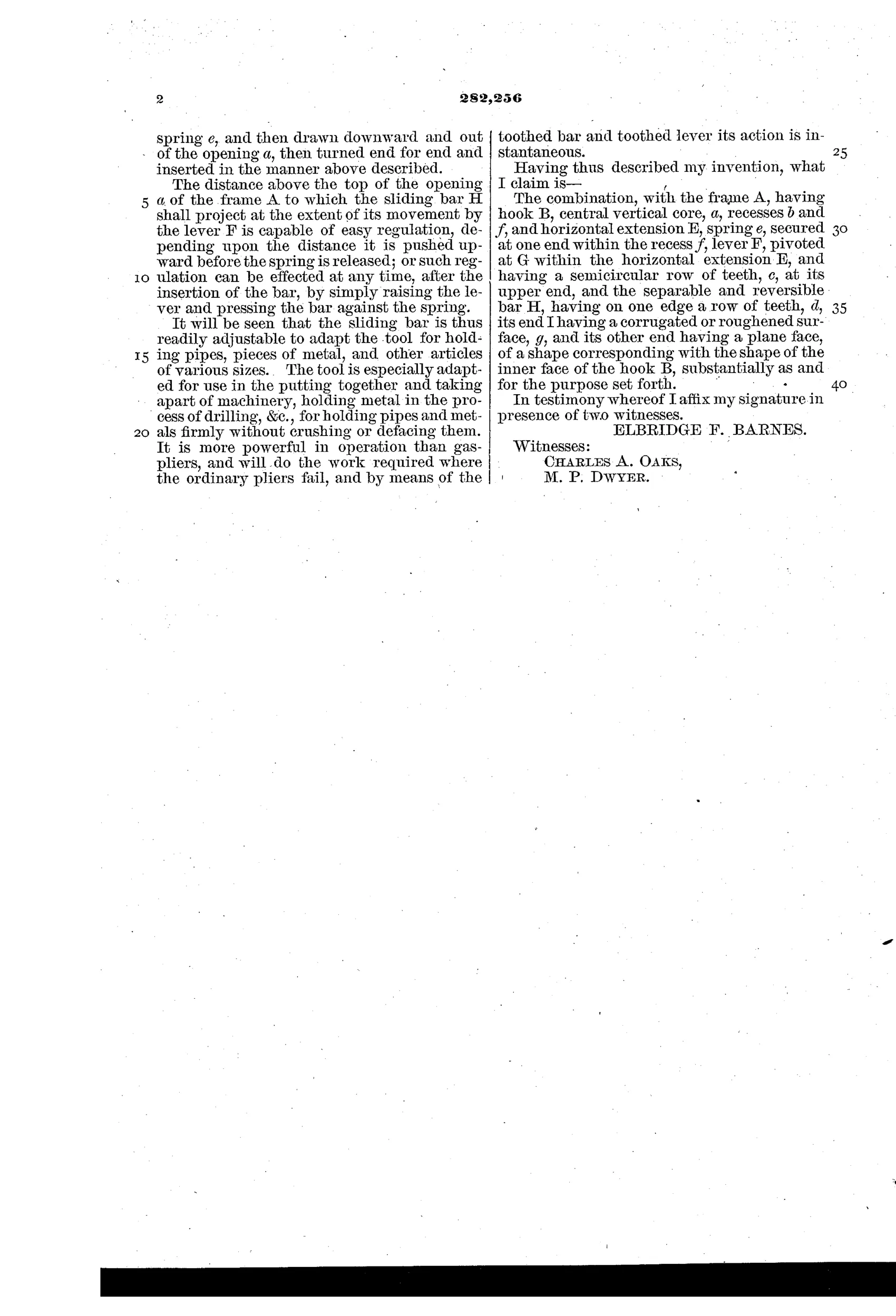
“The combination, with the frame A, having hook B, central vertical core, a, recesses b and f, and horizontal extension E, spring e, secured at one end within the recess f, lever F, pivoted at G within the horizontal extension E, and having a semicircular row of teeth, c, at its upper end, and the separable and reversible bar H, having on one edge a row of teeth, d, its end I having a corrugated or roughened surface, g, and its other end having a plane face, of a shape corresponding with the shape of the inner face of the hook B, substantially as and for the purpose set forth.”
In plain English: The claim covers the overall combination of a cast frame with a hooked jaw, a spring-loaded pivoting toothed lever, and a reversible sliding bar that can be flipped to switch the tool between pipe-tongs and wrench functions.
⚙ In the inventor’s words
“It is more powerful in operation than gas-pliers, and will do the work required where the ordinary pliers fail, and by means of the toothed bar and toothed lever its action is instantaneous.”— Elbridge F. Barnes, from the specification
Fate unknown
No manufactured example or catalog listing is known to me; a marked specimen or trade-catalog entry would settle it.
⚙ Commentary
Barnes's trick here is the reversible bar H. Most combination tools of the era bolt two functions onto opposite ends of one handle; Barnes instead makes one sliding element do double duty. Pull the toothed bar out, flip it, and the working end changes character — a roughened face for biting pipe, or a plane face matched to the hook's flat side for squaring up on a nut. That's economical design: one frame, one lever, one bar, two tools.
The closing action is worth a second look in Fig. 2. The pivoted lever F carries a semicircular row of teeth at its upper end that mesh with the rack cut into the bar, so squeezing the handles drives the bar straight up the frame's central core. A spring tucked in a recess keeps the rack pressed into engagement, which is what lets Barnes claim 'instantaneous' action — the bar can be shoved to the work quickly, then the lever cinches it tight. It's essentially a rack-and-sector quick-adjust, the same family of thinking that would fill wrench patents through the 1890s.
The weak point is the same one that haunts every reversible-part tool: the loose bar. A plumber who drops that bar in a crawlspace owns a hook on a stick. Clever on paper, fussy in a tool bag — which is likely where it stayed. DATAMP has the record for anyone chasing it further.
Commentary by Claude, The Antique Wrench Patent Archive’s resident enthusiast