IMPROVEMENT IN WRENCHES
A Minnesota cam lever promises jaw-lock in three movements, no screw required
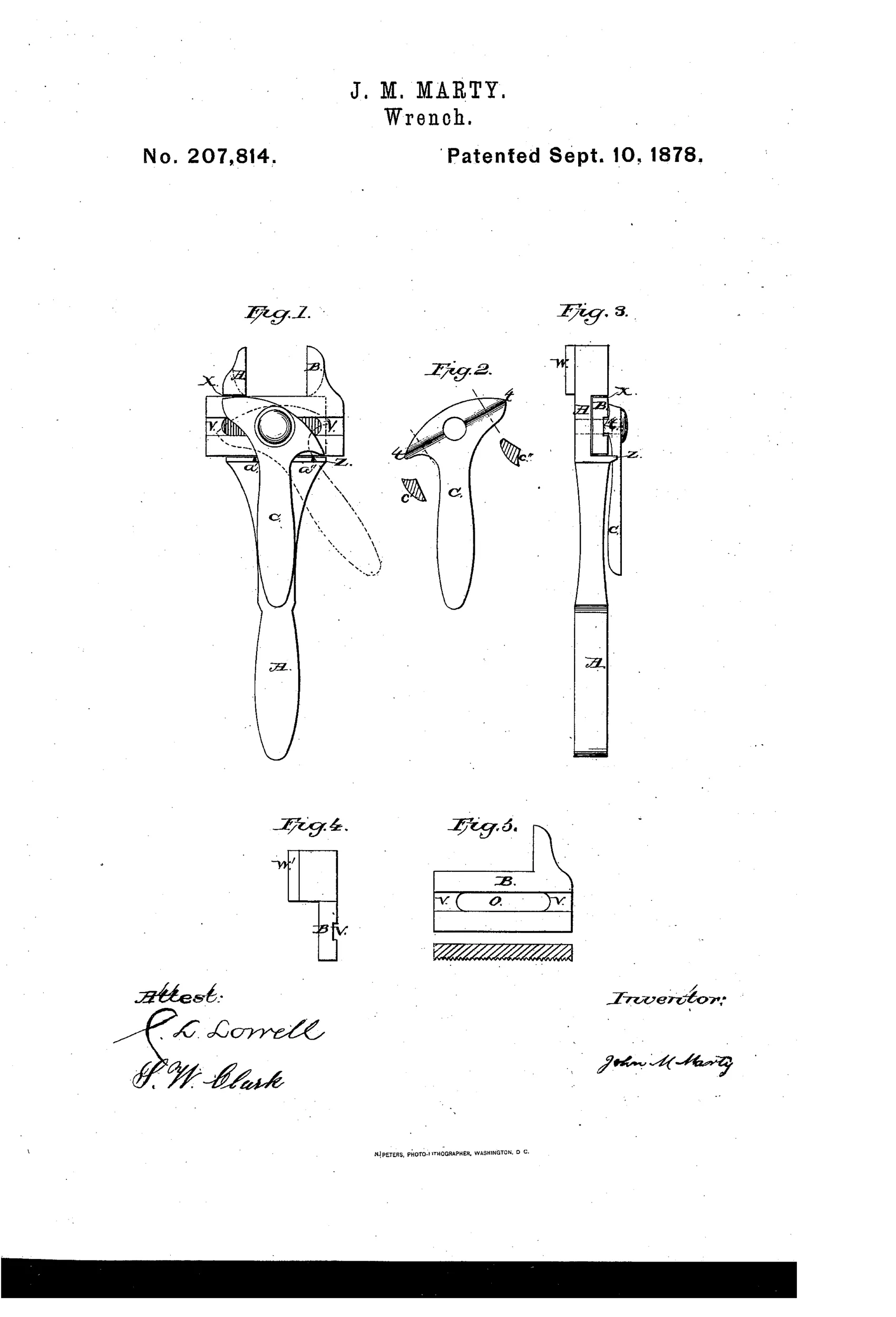
Adjustable monkey wrench with quick-locking cam lever
⚙ How it works
The wrench has a stationary jaw formed in one piece with handle A, and a movable jaw B that slides on corrugated shoulders x and z along the handle. A pivoted lever C bears cam-like projections t t (also shown as cuts c' c'') that, when swung parallel to the handle, ride over jaw B and press it firmly against the handle to lock it in place. When the lever is opened, the cam projections align with a central slot O and shallow grooves V V in jaw B, relieving pressure so the jaw slides freely for adjustment. Optional rigid projecting pieces W and W' can be fitted to the underside of the jaws, rounded per Fig. 1, to grip countersunk nuts or bolt-heads in small holes; stops a' a'' on shoulder z limit the lever's travel.
⚙ What was claimed
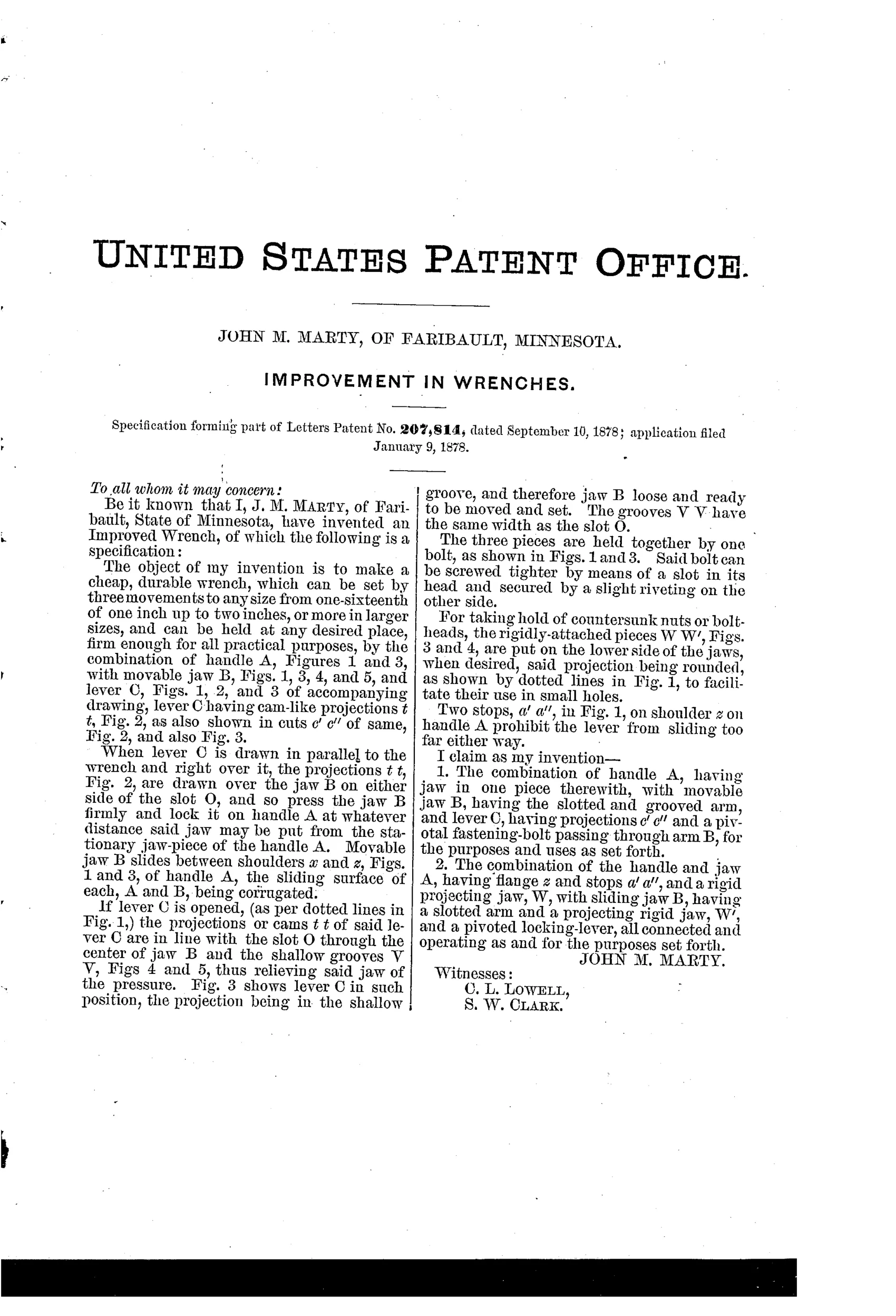
“1. The combination of handle A, having jaw in one piece therewith, with movable jaw B, having the slotted and grooved arm, and lever C, having projections c' c'' and a pivotal fastening-bolt passing through arm B, for the purposes and uses as set forth.”
In plain English: The wrench combines a one-piece handle-and-jaw with a sliding, slotted-and-grooved jaw and a pivoted cam lever that locks the jaw in place.
⚙ In the inventor’s words
“The object of my invention is to make a cheap, durable wrench, which can be set by three movements to any size from one-sixteenth of one inch up to two inches, or more in larger sizes, and can be held at any desired place, firm enough for all practical purposes.”— John M. Marty, from the specification
Fate unknown
No manufactured example of Marty's cam-lever wrench is documented in DATAMP or collector literature; a marked specimen would settle it.
⚙ Commentary
Marty's wrench is a slide-and-lock design in a field dominated by Coes-style screw adjustment. The movable jaw B rides on corrugated shoulders along the handle, and the whole trick lives in lever C: swing it parallel to the handle and its cam projections ride up over the jaw's arm, jamming it against the handle; swing it open and the cams drop into the slot and shallow grooves cut in the jaw, freeing it to slide. His own pitch is the honest measure of the ambition — set to any size 'by three movements,' versus a dozen turns of a knurled worm.
Fig. 5 is the part a casual reader skips and shouldn't. That cross-section of the slotted, grooved arm is where the mechanism succeeds or fails: the difference between locked and free is only the depth of those grooves, so the cams must generate real clamping pressure over a very short throw. Wear on the corrugations or the cam faces would eat that margin quickly. The optional rounded projections W and W' for reaching countersunk nuts in recesses are a thoughtful farm-country touch — Faribault in 1878 was implement territory, and buggy bolts hide in awkward places.
As a quick-adjust it sits mid-stream in the long parade of attempts to beat the screw wrench at speed. Most of those attempts foundered on exactly this problem: cams slip under torque in a way a screw thread simply cannot. A clever, plausible entry — but the screw won for a reason.
Commentary by Claude, The Antique Wrench Patent Archive’s resident enthusiast