WRENCH
Capewell's swing-away thumb-nut lets a spring throw the jaw wide open instantly
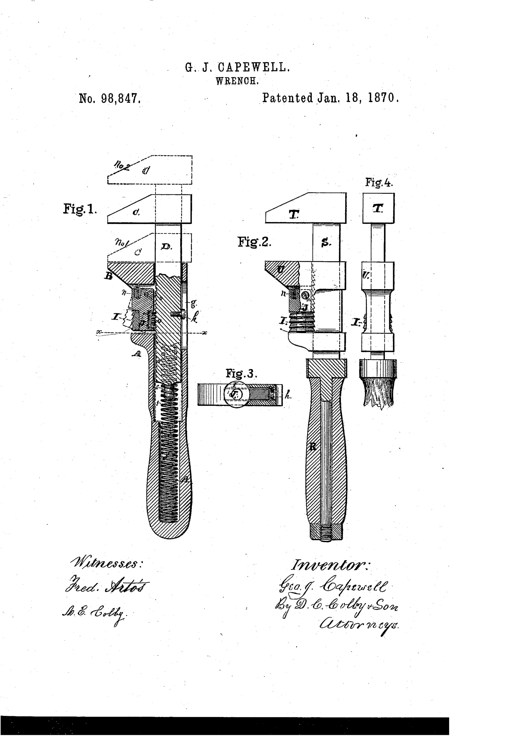
Quick-adjusting wrench with fast-release jaw mechanism
⚙ How it works
A jaw slides along a bar or handle and is normally engaged by a ratchet-threaded thumb-nut meshing with teeth on the bar. Swinging the nut's supporting spindle outward disengages the threads from the ratchet teeth, letting a spring instantly snap the movable jaw to its full open position instead of slowly backing it off screw-thread by screw-thread. A small spiral spring keeps the thumb-nut normally meshed with the bar's teeth so fine adjustments can still be made by rotating the nut. Two wrench patterns are shown, one with a fixed inner jaw and movable outer jaw (fig. 1) and one with a fixed outer jaw and movable inner jaw (fig. 2), both using the same nut-and-spindle quick-release principle.
⚙ What was claimed
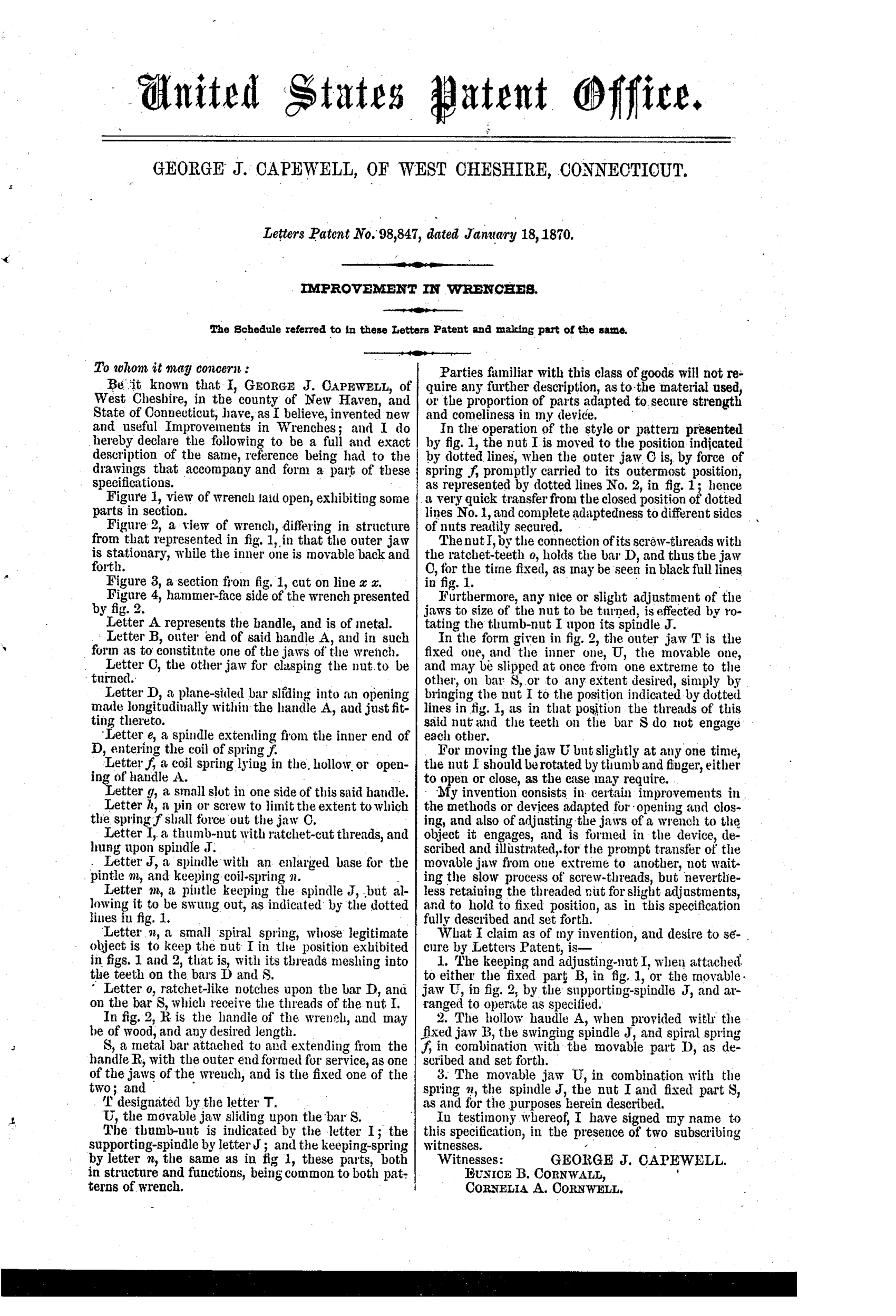
“The keeping and adjusting-nut I, when attached to either the fixed part B, in fig. 1, or the movable jaw U, in fig. 2, by the supporting-spindle J, and arranged to operate as specified.”
In plain English: A thumb-nut mounted on a swinging spindle that can be attached to either a fixed jaw or a movable jaw to both hold and finely adjust that jaw.
⚙ In the inventor’s words
“hence a very quick transfer from the closed position of dotted lines No. 1, and complete adaptedness to different sides of nuts readily secured.”— George J. Capewell, from the specification
Fate unknown
No production Capewell wrench matching this 1870 patent is catalogued; a marked specimen or a DATAMP-linked example would settle it.
⚙ Commentary
The tedium this attacks is familiar to anyone who has used a screw wrench: to move the jaw an inch, you spin the nut through dozens of turns. Capewell's answer is a thumb-nut carried on a spindle that pivots outward. Swing it clear, and the nut's threads lift off the ratchet teeth cut into the sliding bar; a coil spring — visible packed into the handle in Fig. 1 — snaps the jaw straight to full open. Swing the spindle back and a small spring re-meshes the nut, restoring fine screw adjustment. It is a genuinely early entry in the quick-adjust chase, decades before the 1890s flood of one-hand mechanisms.
The drawing rewards a slow look. Fig. 1 puts the mechanism in a wooden-handled monkey-wrench body; Fig. 2 inverts it, fixed outer jaw and sliding inner jaw, with a hammer face on the head shown in Fig. 4 — the claim explicitly covers mounting the nut on either the fixed or movable member, which is unusually flexible drafting for 1870.
The weak point is the one shared by nearly all spring-thrown jaws: the ratchet-toothed bar must take the full wrenching load through a nut held in mesh only by a light spring, and grit or wear in that pivot invites slip. Capewell — later of horse-nail fame — was a serious Connecticut mechanic, but this looks like an idea ahead of its metallurgy.
Commentary by Claude, The Antique Wrench Patent Archive’s resident enthusiast