SCREW-WRENCH
A half-turn thumb-piece disengages the screw — quick-adjust, fourteen years after Coes
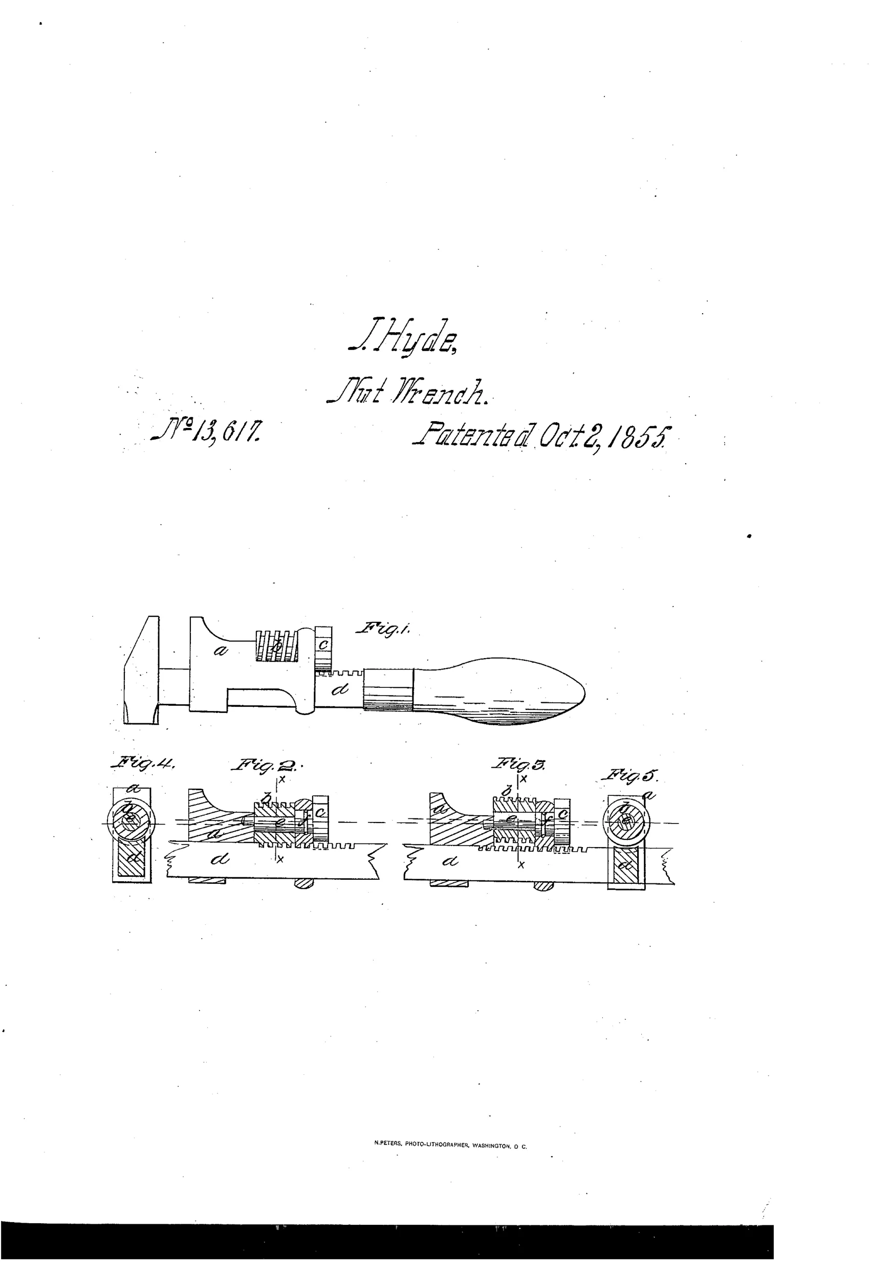
Adjustable screw-wrench with disengageable eccentric-shaft screw jaw
⚙ How it works
The moving jaw fits closely against a bar that has a spiral rack cut into its front side instead of a screw-cut edge. A short screw with a central hole seats in the jaw and is engaged by an eccentric shaft; turning the shaft a half revolution raises the screw out of the rack, letting the jaw slide freely on the bar. A thumb-piece on the shaft both turns it and acts as a stop to limit rotation, while a pin in a groove on the shaft's largest bearing holds it captive in the jaw. The inventor prefers V or beveled threads over square threads so the screw will always mesh with the rack rather than striking tooth-on-tooth.
⚙ What was claimed
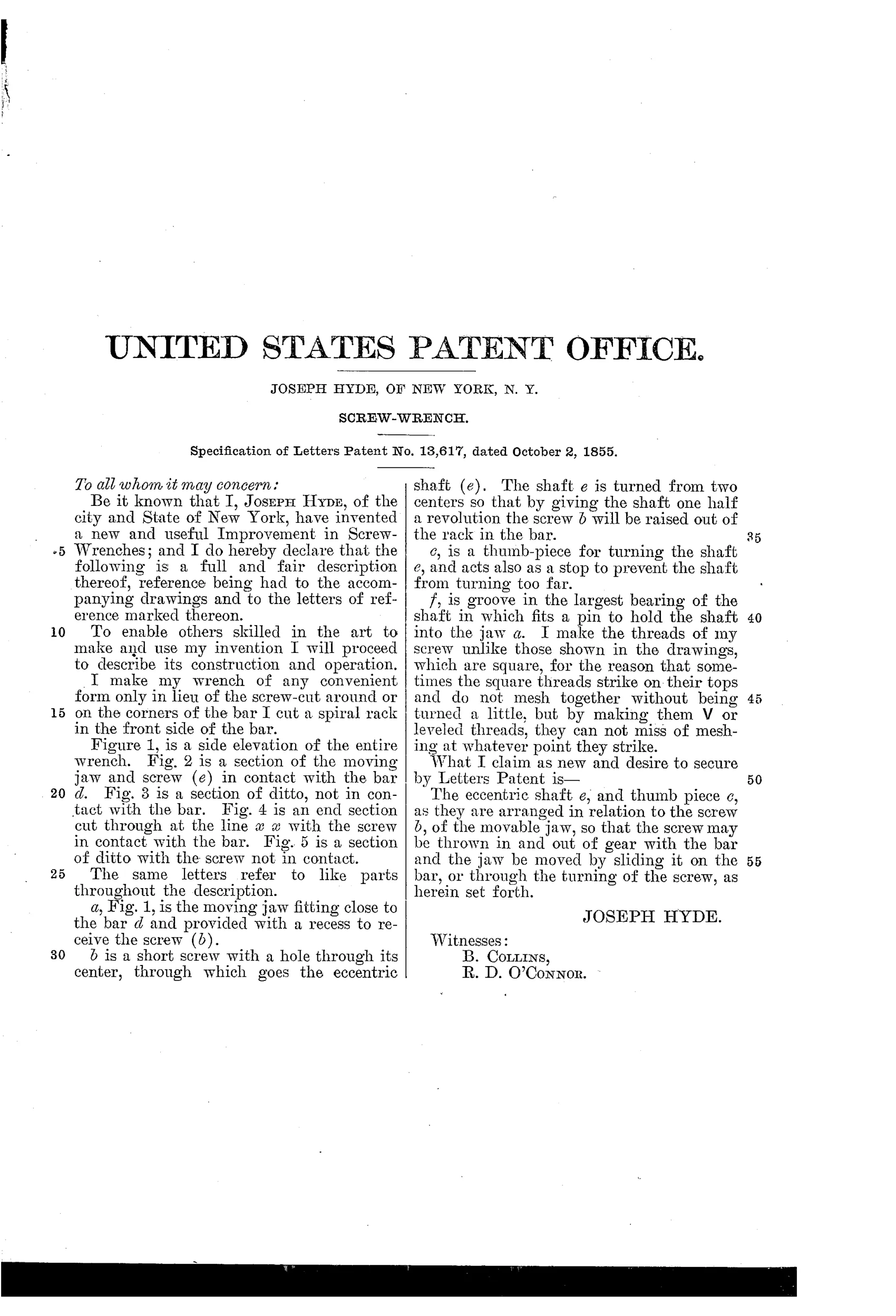
“The eccentric shaft e, and thumb piece c, as they are arranged in relation to the screw b, of the movable jaw, so that the screw may be thrown in and out of gear with the bar and the jaw be moved by sliding it on the bar, or through the turning of the screw, as herein set forth.”
In plain English: He claims the combination of an eccentric shaft and thumb-piece that lets the operator either slide the jaw freely along the bar or lock it in place by turning a screw into the bar's rack.
⚙ In the inventor’s words
“I make the threads of my screw unlike those shown in the drawings, which are square, for the reason that sometimes the square threads strike on their tops and do not mesh together without being turned a little, but by making them V or leveled threads, they can not miss of meshing at whatever point they strike.”— Joseph Hyde, from the specification
Fate unknown
No manufactured example of Hyde's wrench is catalogued in DATAMP or the collector literature; a marked specimen would settle it.
⚙ More by Joseph Hyde
- Wrench. (1858)
⚙ Commentary
By 1855 the Coes pattern had settled what a screw wrench looked like: knurled worm at the handle, jaw creeping up and down as fast as your thumb could spin it. Hyde's complaint is implicit but obvious — that creeping is slow. His answer is a screw with a hole bored through its center, seated in the moving jaw and riding on an eccentric shaft. Give the thumb-piece a half turn and the eccentric lifts the whole screw clear of the spiral rack cut into the bar; the jaw now slides freely to the nut, and another half turn drops the screw back in for fine adjustment and lock-up. The thumb-piece doubles as its own rotation stop, and a pin running in a groove keeps the shaft captive — tidy detailing for such an early entry.
The part a casual reader will skip is the best part: Hyde admits the square threads shown in his own drawings are wrong. Square threads can land tooth-on-tooth and refuse to mesh; V or beveled threads will always find their way into the rack at whatever point they strike. That is a man who actually tried the thing, or thought like one.
This is essentially the quick-adjust idea the 1880s and 90s would chase with cams, pawls, and spring plungers — stated plainly a generation early. Whether an eccentric small enough to fit the jaw could hold the screw rigid under real torque is the open engineering question; any rock in that shaft becomes slop at the jaw.
Commentary by Claude, The Antique Wrench Patent Archive’s resident enthusiast