IMPROVEMENT IN WRENCHES
The whole jaw assembly swings around the pinion — handle pull does the gripping
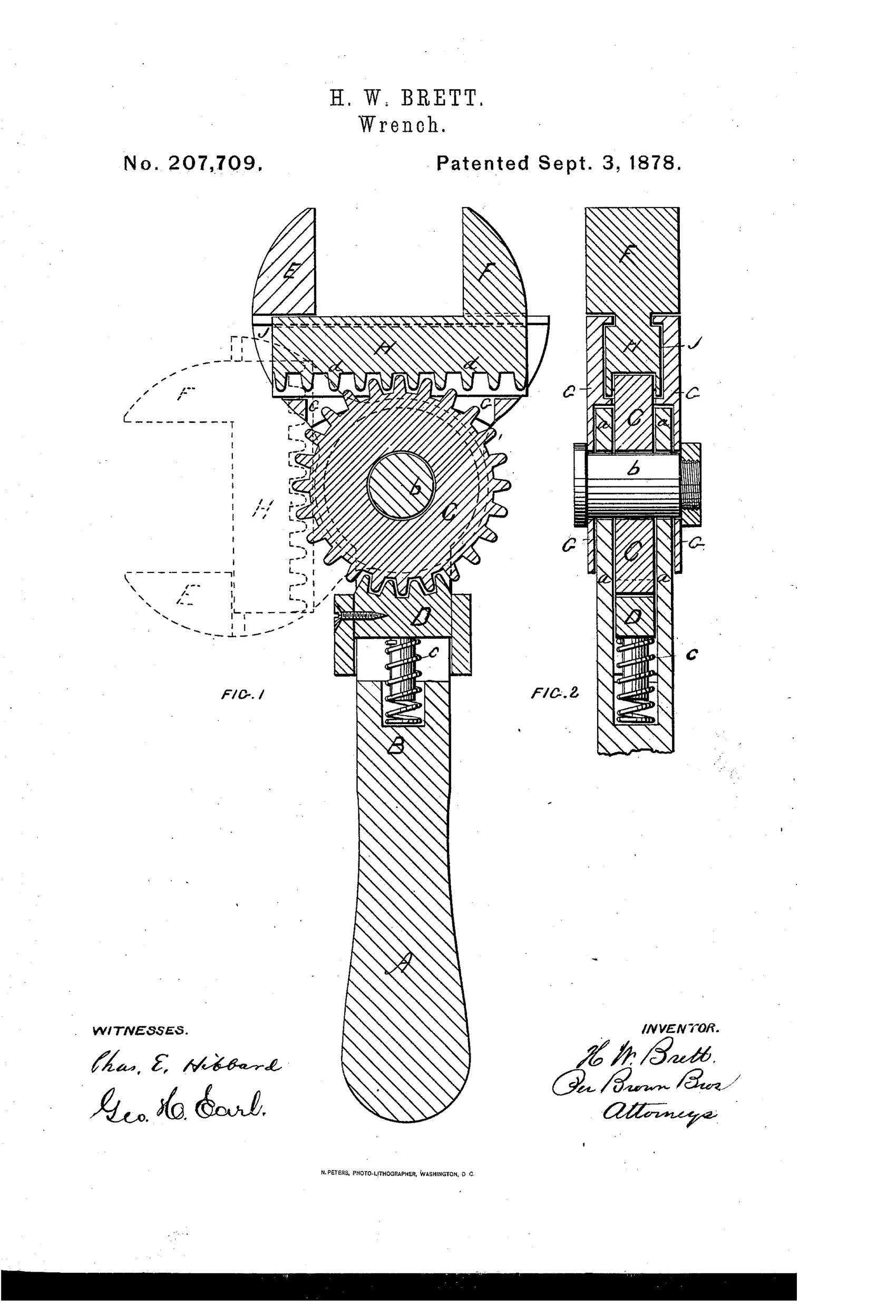
Adjustable pinion-and-rack gear-driven wrench
⚙ How it works
A shank-bar carries a loose pinion-gear wheel at one end, held from turning by a spring-loaded pawl-block that engages the pinion's teeth. One jaw pivots on the same center as the pinion, while the other jaw slides through the first jaw and has a cog-rack that meshes with the pinion's teeth. Releasing the pawl-block lets the jaws swing freely to either side or end of the shank-bar; once positioned, pulling or pushing the handle turns the pinion via the rack, opening or closing the jaws to grasp the work.
⚙ What was claimed
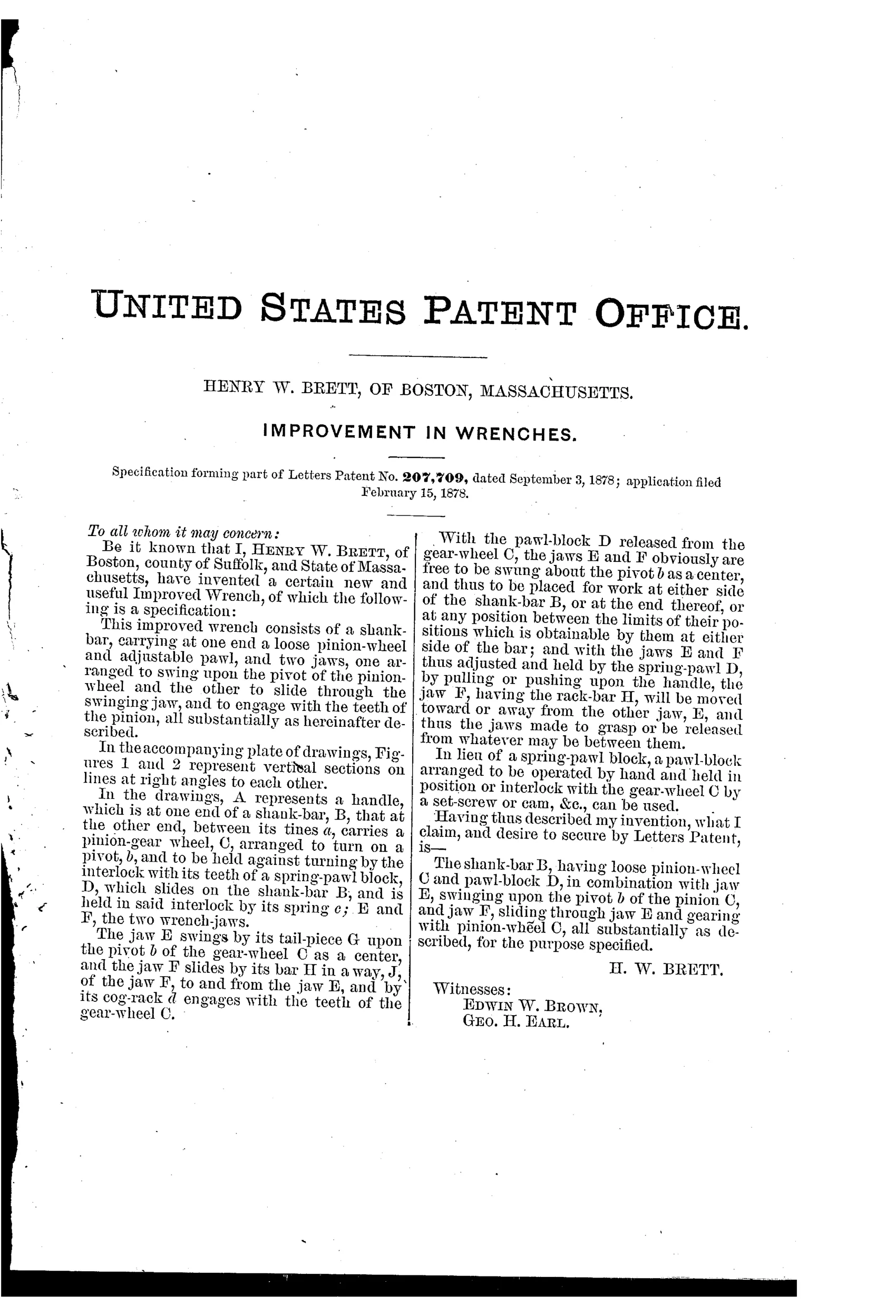
“The shank-bar B, having loose pinion-wheel C and pawl-block D, in combination with jaw E, swinging upon the pivot b of the pinion C, and jaw F, sliding through jaw E and gearing with pinion-wheel C, all substantially as described, for the purpose specified.”
In plain English: The claim covers a wrench handle with a free-spinning pinion gear and a locking pawl, combined with one jaw that pivots on the pinion's axle and a second jaw that slides through the first and meshes with the pinion's teeth.
⚙ In the inventor’s words
“With the pawl-block D released from the gear-wheel C, the jaws E and F obviously are free to be swung about the pivot b as a center, and thus to be placed for work at either side of the shank-bar B, or at the end thereof, or at any position between the limits of their positions which is obtainable by them at either side of the bar.”— Henry W. Brett, from the specification
Fate unknown
No catalogued or surviving example of this Boston design is documented on DATAMP; a marked specimen would settle it.
⚙ Commentary
Brett's wrench puts the adjustment gear at the pivot point, and that one decision produces two tricks at once. The pinion sits loose on the shank-bar's stud, locked only by a spring-loaded pawl-block down in the handle. The pivoting jaw turns on that same stud, and the sliding jaw's rack meshes with the pinion. Release the pawl and the entire head swings free — either side of the handle or straight off the end, as the dashed ghost jaws in Fig. 1 show. Lock the pawl, and pulling or pushing the handle rolls the fixed pinion along the rack, driving the jaws open or shut against the work.
That second behavior is the interesting part: it's a self-tightening action, close in spirit to the later chain and pipe wrenches where handle torque feeds the grip. The harder you pull, the more the rack tries to walk along the pinion, closing the jaws. Whether it releases as gracefully is another question — a wrench that jams tighter under load can be stubborn about letting go, and the small pawl-block carries the whole reaction torque through gear teeth of modest size.
As a piece of the 1870s adjustment-mechanism festival, this is one of the more ambitious entries: not a refinement of the Coes screw but a genuine rethink, trading the knurled worm for geometry. Likely too many machined parts for the price a wrench had to sell at, which is the usual fate of the clever ones.
Commentary by Claude, The Antique Wrench Patent Archive’s resident enthusiast