IMPROVEMENT IN PIPE-WRENCHES WITH CUTTERS.
One handle, two heads: swap the pivot bolt to trade cutter for wrench
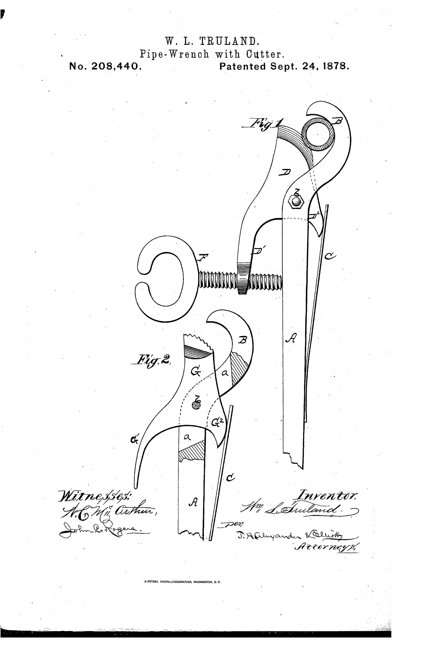
Combination pipe wrench with built-in pipe cutter
⚙ How it works
The handle A forms a jaw B and carries a slotted, curved head into which a cutting blade D pivots on a bolt b. The blade's heel D2 passes through the slot and is pressed by a spring C, while a thumb-screw F on the blade's arm bears against the handle to force the cutting edge into the pipe. A separate serrated wrench-jaw G, with arm G1 and heel G2, can be swapped in place of the cutter by removing bolt b, letting the same spring C throw jaw G against the pipe for turning. Turning screw F advances the cutter for cutting; arm G1 is used only to release the wrench from the pipe.
⚙ What was claimed
“The cutting-blade D, constructed with arm D1 and heel D2, the arm being provided with screw F on one side of lever A, and the heel having the pressure-spring C on its opposite side, substantially as and for the purpose herein set forth.”
In plain English: The claim covers a cutting blade with an arm and heel, where a screw on the arm and a spring on the heel work together on opposite sides of the handle to press the blade into the pipe.
⚙ In the inventor’s words
“This tool or implement is simple and cheap in construction, durable, and not liable to get out of order.”— William L. Truland, from the specification
Fate unknown
No manufactured example or catalog listing is documented in DATAMP or the collector literature; a marked specimen would settle it.
⚙ Commentary
Truland's idea is honest and economical: a plumber turning pipe usually has to cut it too, so why carry two tools? His handle A ends in a hooked jaw B, and the working head — either the cutting blade D or the serrated wrench jaw G — pivots on a single bolt b. Pull the bolt, swap the head, and the same spring C that threw the cutter into the pipe now throws the toothed jaw against it. That spring-loaded heel is the neat part: it gives the wrench jaw a self-gripping, ratchet-like bite, the same principle that makes later spring pipe wrenches so pleasant to use one-handed.
The drawing rewards a close look. In Fig. 1 the thumb-screw F on the blade's arm bears against the handle, feeding the cutting edge in as you rotate around the pipe — a genuine pipe-cutter action, not just a knife pressed by hand. In Fig. 2 the arm G1 exists only to release the sprung jaw, an admission that a good self-gripper needs a way to let go.
The weakness is the swap itself. Removing and reinserting a pivot bolt on a wet job site, with a loose spring in play, is exactly the fiddly step working plumbers won't tolerate. Combination pipe tools were a crowded chase in the 1870s, and the ones that survived kept both functions on the tool at once. This is a thoughtful dead end.
Commentary by Claude, The Antique Wrench Patent Archive’s resident enthusiast