IMPROVEMENT IN WRENCHES
Twist the handle, and a cam frees the jaw to slide anywhere
Quick-adjust monkey wrench with cam-locking lever
⚙ How it works
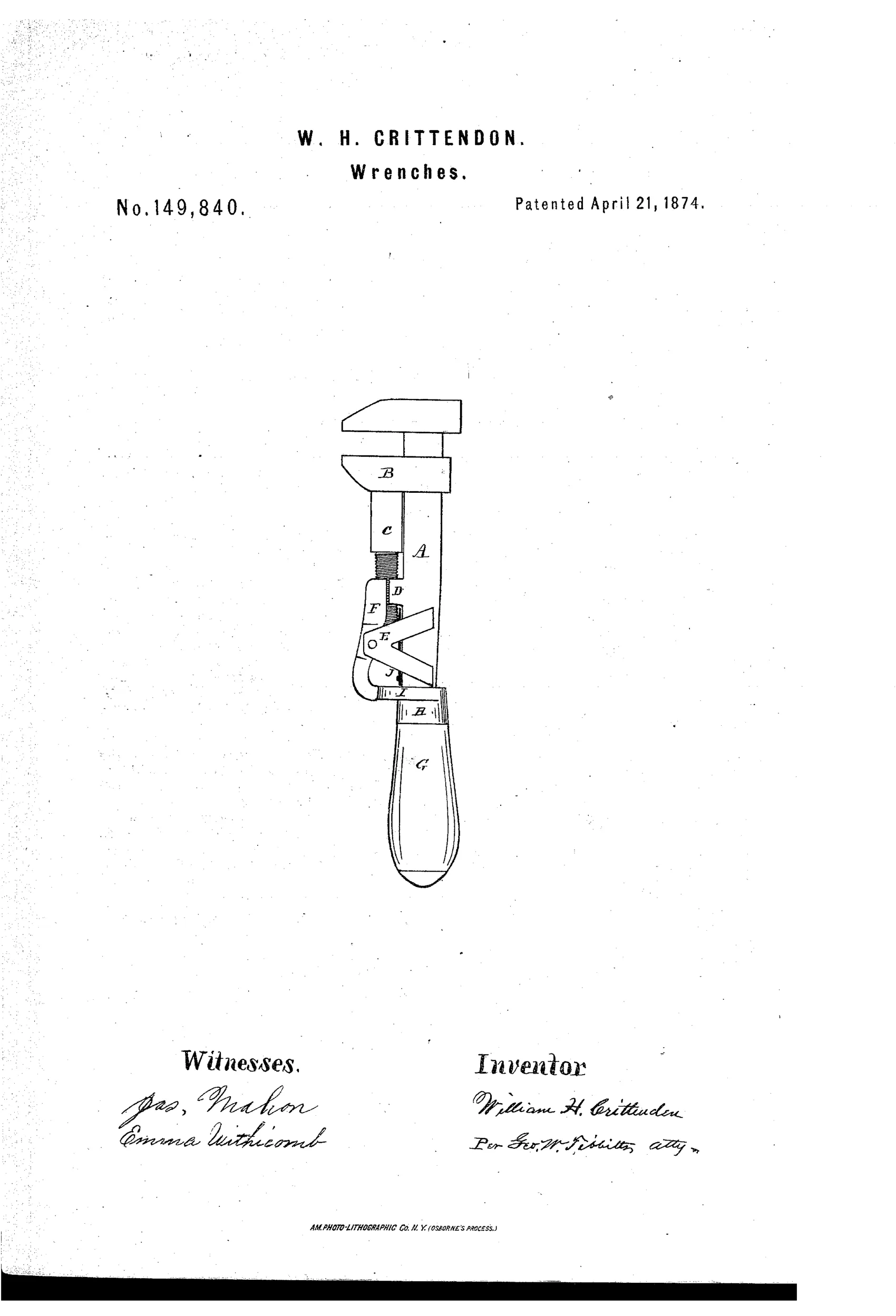
A movable jaw B rides on a threaded arm C parallel to the main lever A and is held by a half-nut D. A pivoted lever F engages a groove on the threaded arm, and a cam-ferrule H,I on the handle G forces lever F down to lock the jaw in place. Turning the handle rotates the cam away from lever F, releasing it so a spring J lifts the arm out of the half-nut threads, letting the jaw slide freely for quick repositioning; turning the handle back reapplies the cam to lock it firmly again.
⚙ What was claimed
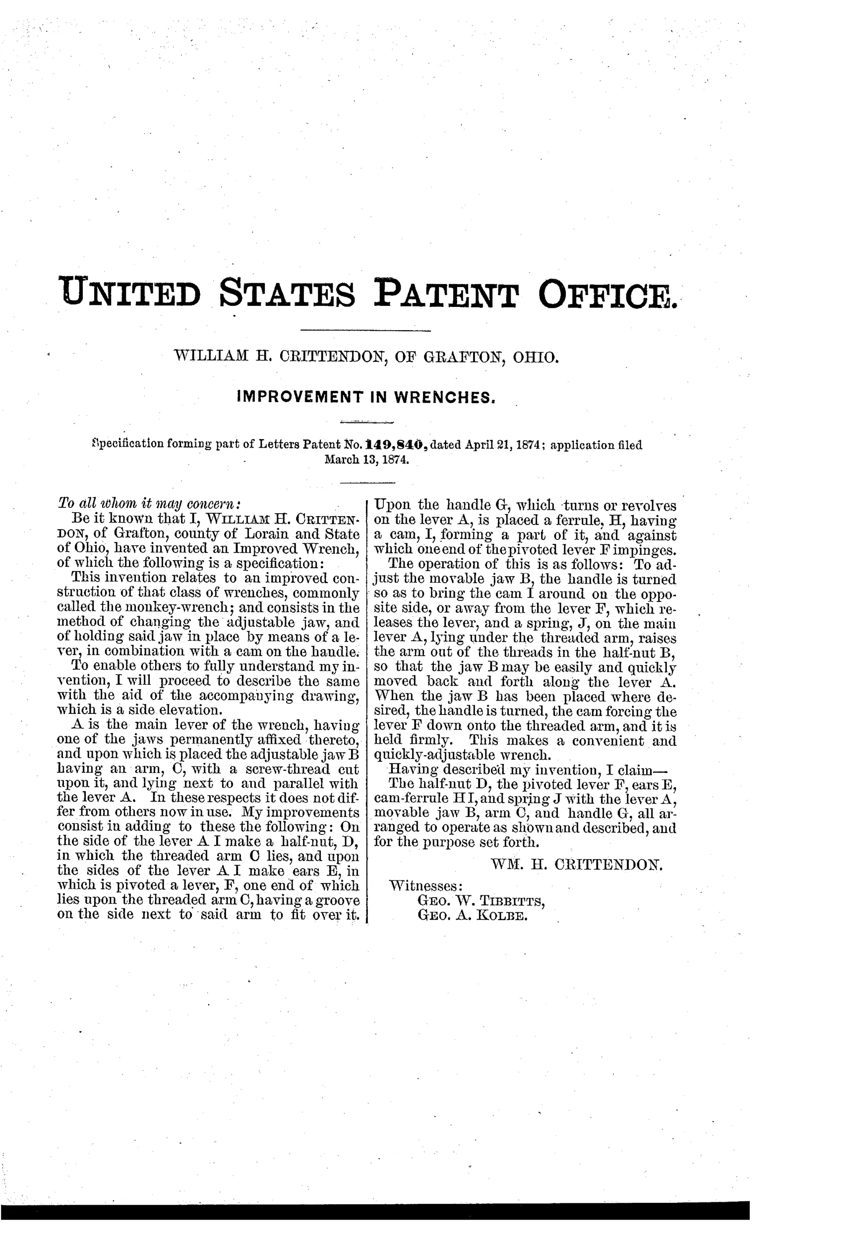
“The half-nut D, the pivoted lever F, ears E, cam-ferrule H I, and spring J with the lever A, movable jaw B, arm C, and handle G, all arranged to operate as shown and described, and for the purpose set forth.”
In plain English: The combination of the half-nut, pivoted locking lever, ears, cam-ferrule, and spring with the lever, movable jaw, threaded arm, and handle, arranged to work together as described.
⚙ In the inventor’s words
“This makes a convenient and quickly-adjustable wrench.”— William H. Crittendon, from the specification
Fate unknown
No manufactured example or catalogue listing is documented; a surviving wrench marked with the 1874 patent date would settle it.
⚙ Commentary
Crittendon's answer to the quick-adjust problem is a handle that does double duty. The threaded arm C carries the movable jaw, and a half-nut D grips those threads to hold adjustment — standard fare so far. The trick is the release: a pivoted lever F bears on the arm, and a cam-ferrule at the top of the wooden handle presses that lever down to keep everything locked. Rotate the handle a fraction and the cam swings clear; spring J then lifts the threaded arm out of the half-nut entirely, and the jaw slides freely to any opening. Twist back, and the cam clamps it all tight again.
It's a genuinely one-hand mechanism, which is what everyone in this era was chasing — Coes-style screw adjustment is precise but slow, and pipe fitters and machinists wanted to slap the jaw against the work. The drawing rewards a close look at the cluster around E, F, and J: the pivoted lever, its ears, and the spring are all packed into the throat where the handle meets the shank, which is exactly where wrenches take their bending load.
That's also my worry. A cam-held half-nut relies on the handle staying put under torque, and heavy use has a way of walking cam ferrules loose. Clever geometry, but the load path through a pivoted lever is a lot less reassuring than a solid nut on solid threads.
DATAMP lists the patent; I know of no marked example.
Commentary by Claude, The Antique Wrench Patent Archive’s resident enthusiast