IMPROVEMENT IN PIPE-WRENCHES.
A spring hides inside the tongue, keeping the jaw cocked no matter what
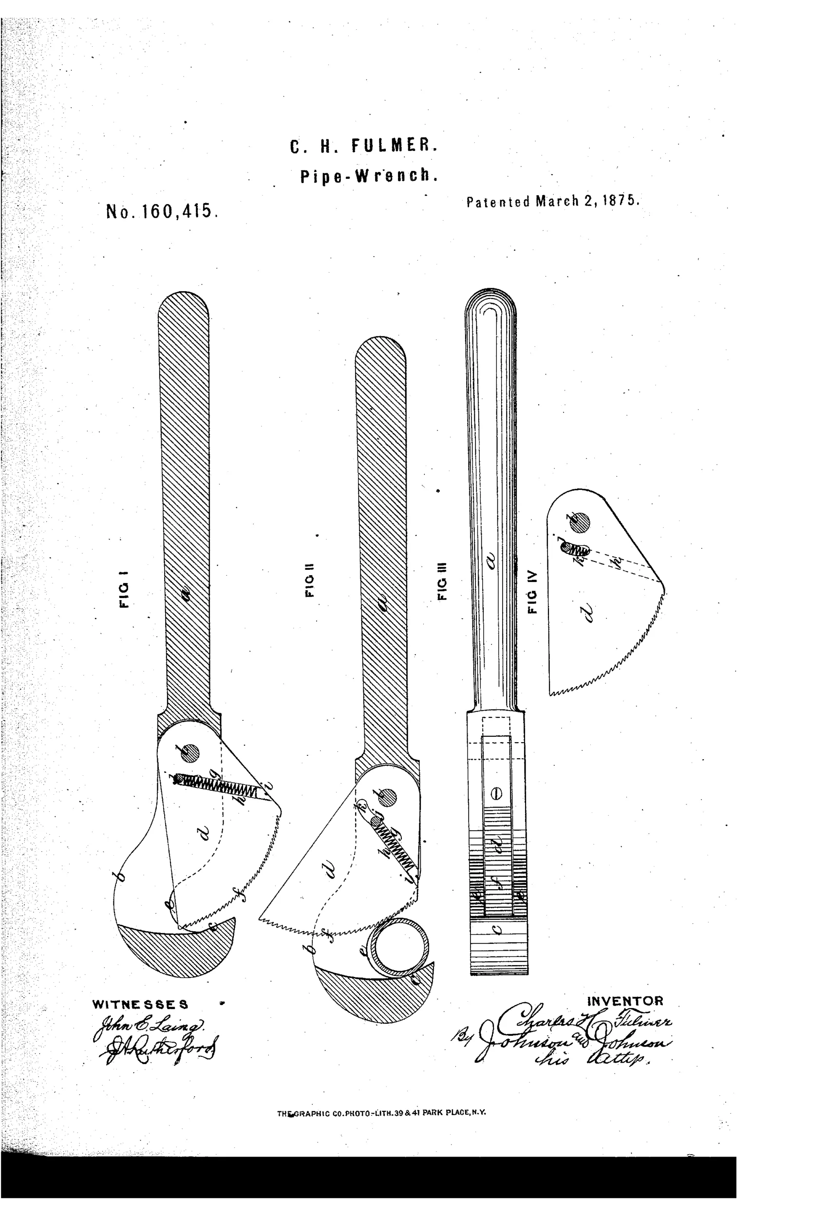
Spring-loaded self-adjusting pipe wrench jaw mechanism
⚙ How it works
The jaw-bar has a goose-neck ending in an angular hook that forms one side of the pipe-gripping jaw, while a serrated tongue is pivoted within a slot in the jaw-bar so it can open and close from the back or seat side. A spiral spring fixed inside the tongue bears against a fixed pin in the jaw-slot, constantly pressing the tongue forward toward the hook so it is always ready to grip the pipe regardless of how the wrench is handled. As the wrench is applied, the pipe pushes the tongue backward against the spring, and the curved biting surface increases its distance from the hook proportionally, automatically accommodating different pipe sizes. A slot in the tongue, cut on a curve struck from the tongue's pivot pin, limits and guides this movement, and the fixed pin also acts as a stop to prevent the serrated edge from striking and dulling against the hook.
⚙ What was claimed
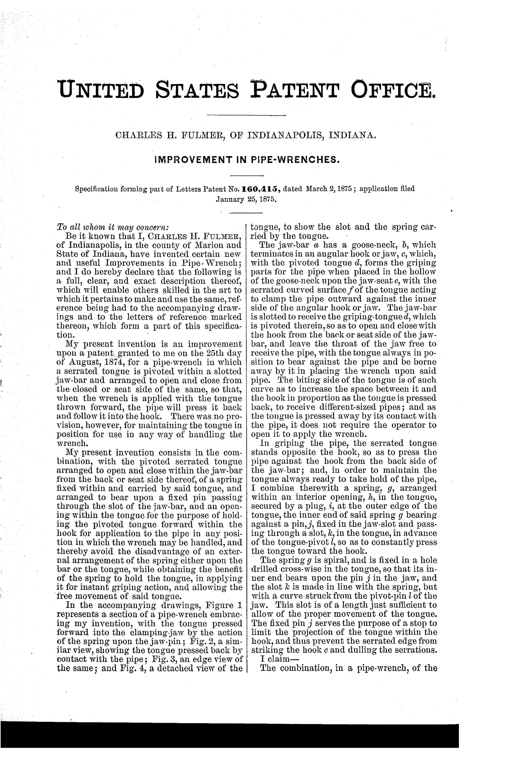
“The combination, in a pipe-wrench, of the pivoted tongue d, arranged to open and close with the jaw, as described, of a spring, g, fixed within and carried by said tongue and a fixed bearing-pin, j, in the jaw for said spring, whereby the tongue is always held in position for use without regard to the manner in which the wrench is handled.”
In plain English: The invention claims a pipe wrench jaw with a spring built into the pivoting tongue that presses against a fixed pin, keeping the tongue always ready to grip the pipe no matter how the wrench is held or used.
⚙ In the inventor’s words
“There was no provision, however, for maintaining the tongue in position for use in any way of handling the wrench.”— Charles H. Fulmer, from the specification
Fate unknown
No manufacturer or marked example is documented in the usual references; a surviving specimen or a period hardware listing would settle it.
⚙ Commentary
Fulmer's problem statement is refreshingly narrow. Pivoted-tongue pipe wrenches already existed — a serrated gripping piece hinged in the jaw-bar so the pipe itself could rock it into bite. The trouble was that gravity ran the mechanism: turn the wrench over, or carry it head-down, and the tongue flopped out of position. His fix is to bury a spiral spring inside the tongue itself, bearing against a fixed pin in the jaw slot, so the tongue is always pressed toward the hook and always ready to close on a pipe regardless of orientation.
The drawing rewards a slow look. Figures I and II are the before-and-after: tongue sprung forward, then shoved back by the pipe with the curved serrated face opening the gap proportionally to pipe diameter — a genuinely self-adjusting jaw with no screw anywhere. Figure IV shows the neat detail that the tongue's guide slot is struck on a curve from its own pivot pin, and that the same fixed pin doubles as a stop so the teeth can never slam into the hook and dull themselves. That is careful, economical design.
Where it sits: an 1870s refinement in the long line of self-gripping pipe wrenches that eventually lost out to the Stillson pattern (patented 1869 and already spreading). Fulmer's wrench would work on a limited size range, but the Stillson's positive screw adjustment plus floating jaw covered more ground with less delicacy. A clever dead-end branch, honestly argued.
Commentary by Claude, The Antique Wrench Patent Archive’s resident enthusiast