Fish-Plate-Nut Wrenches
A ratchet wrench that clamps itself to the rail and follows the nut
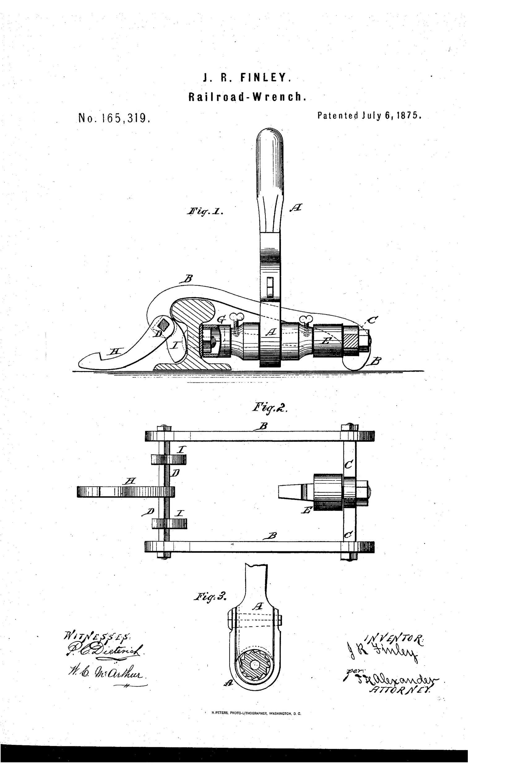
Clamp-mounted ratchet wrench for railroad fish-plate nuts
⚙ How it works
An ordinary ratchet-wrench A is united at one end to a revolving chuck E mounted in a clamp-frame made of curved side bars B B and pivoted cross-bars C and D. A short chuck G on the other end of the wrench receives the nut head, with the wrench working inside the clamp frame. Cross-bar D carries two eccentrics I I and a center hook H forming a foot-piece; the operator places the curved bars over the rail, presses eccentrics against the rail side with his foot on H, and works the ratchet back and forth so the nut screws up while the clamp follows along the rail via pressure-driven eccentric rotation.
⚙ What was claimed
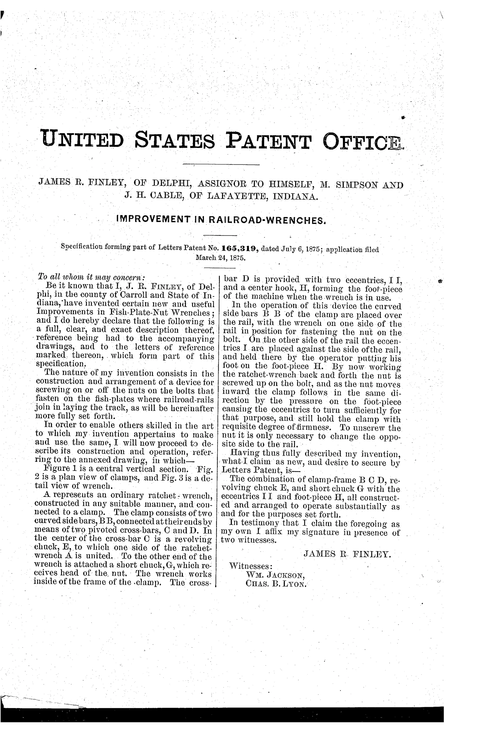
“The combination of clamp-frame B C D, revolving chuck E, and short chuck G with the eccentrics I I and foot-piece H, all constructed and arranged to operate substantially as and for the purposes set forth.”
In plain English: The invention claims a rail-clamping frame combined with two chucks, eccentrics, and a foot-piece that together let a ratchet wrench tighten fish-plate nuts on railroad track.
⚙ In the inventor’s words
“To unscrew the nut it is only necessary to change the opposite side to the rail.”— James R. Finley, from the specification
Fate unknown
No manufactured example or catalogue listing is documented in DATAMP or collector literature; a marked specimen or a railroad supply catalogue entry would settle it.
⚙ Commentary
Most wrench patents in this era chase adjustability. Finley chased something else entirely: reaction force. Anyone who has tightened a fish-plate nut knows the real work isn't turning the wrench, it's bracing your body against every stroke. Finley's answer was to hang the ratchet inside a clamp frame that straddles the rail — the curved side bars B B hook over the rail head, two eccentrics I I bite the rail web, and the operator's foot on the hook H drives them tight. The rail itself absorbs the torque; the trackman just pumps the handle.
The clever detail in Fig. 2 is that the eccentrics are pressure-driven, meaning the clamp is self-locking under load but can creep along the rail between nuts rather than needing full removal and re-setting. The spec's cheerful line about reversing — "to unscrew the nut it is only necessary to change the opposite side to the rail" — shows the ratchet has no reversing pawl; you flip the whole apparatus, which is honest 1875 simplicity.
The weakness is bulk. A section gang carrying track wrenches already had a fast, brutal, cheap tool. This one is a small machine, and railroads were rarely persuaded to buy machines where a heavy wrench and a strong back sufficed. As a dead end it's an instructive one: the problem it solved was real, and powered rail-bolt machines eventually solved it the same way — by anchoring to the rail.
Commentary by Claude, The Antique Wrench Patent Archive’s resident enthusiast