IMPROVEMENT IN WRENCHES
Twist a sleeve, free the jaw: an 1874 one-hand quick-adjust from New York
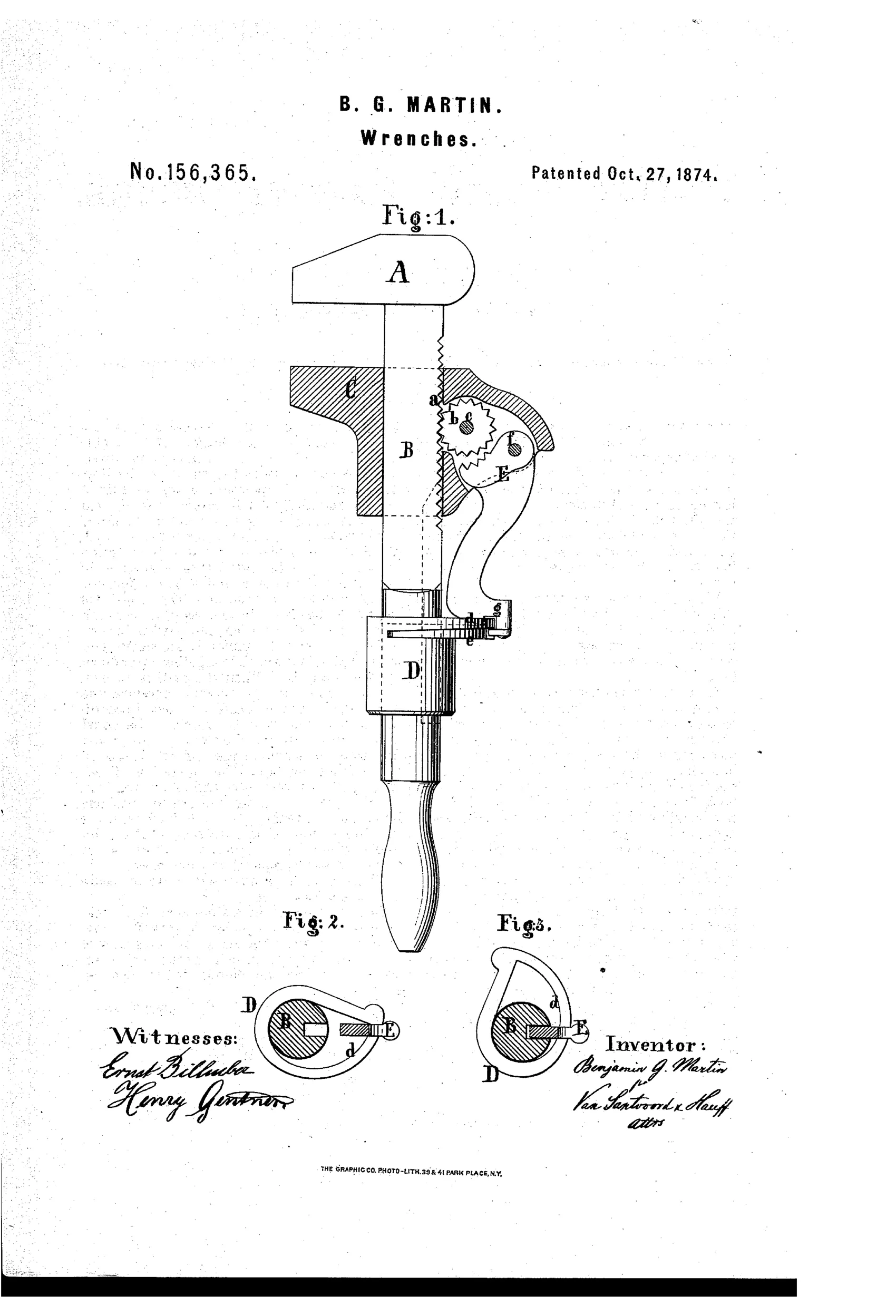
Self-locking adjustable wrench with pawl and pinion
⚙ How it works
A movable jaw rides on a toothed shank and is engaged by a pinion mounted on a pivot pin in the jaw's back. A rotating locking-sleeve carries a double cam that either throws a stop-pawl into gear with the pinion to lock the jaw, or withdraws it to allow free sliding adjustment. Turning the sleeve one way releases the pawl for quick adjustment to the workpiece; turning it the other way locks the jaw firmly in place, all operable with one hand.
⚙ What was claimed
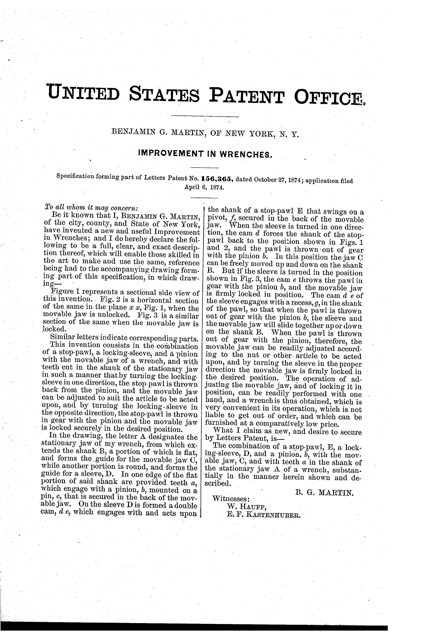
“The combination of a stop-pawl, E, a locking-sleeve, D, and a pinion, b, with the movable jaw, C, and with teeth a in the shank of the stationary jaw A of a wrench, substantially in the manner herein shown and described.”
In plain English: The patent covers combining a locking sleeve, stop-pawl, and pinion with a toothed shank and movable jaw so the wrench can lock or release the jaw as described.
⚙ In the inventor’s words
“The operation of adjusting the movable jaw, and of locking it in position, can be readily performed with one hand, and a wrench is thus obtained, which is very convenient in its operation, which is not liable to get out of order, and which can be furnished at a comparatively low price.”— Benjamin G. Martin, from the specification
Fate unknown
Martin was no established maker and no production version is well known; a marked specimen or a DATAMP-catalogued example would settle it.
⚙ Patented the same day
- IMPROVEMENT IN WRENCHES — William R. Moore
⚙ Commentary
Martin's wrench belongs to the great pre-1900 chase after the one-hand quick-adjust — the mechanism collectors still rank as the intellectual peak of the field. His answer is a three-part chain: teeth cut into the shank, a small pinion carried in the back of the movable jaw, and a stop-pawl that can be thrown into or out of engagement with that pinion by a cam on a rotating sleeve. Twist the sleeve one way and the pawl retreats, letting the jaw slide freely to the nut; twist it back and the pawl locks the pinion, which in turn locks the jaw against the toothed shank.
The clever part is that Martin doesn't try to lock the jaw against the rack directly — he locks the pinion, one gear stage removed. That gives him a small, light pawl doing the work, and the double cam in the sleeve (compare Figs. 2 and 3) makes engagement positive in both directions rather than relying on a spring. The dashed lines in Fig. 1 show the sleeve D wrapped around the shank down near the handle, where the thumb naturally falls.
The weak point is the same one that dogged most rack-and-pawl designs: the jaw's grip is only as fine as the tooth pitch, so it can't cinch down snug the way a Coes screw can. That trade-off — speed versus final tightness — is exactly why the screw wrench kept winning.
Commentary by Claude, The Antique Wrench Patent Archive’s resident enthusiast