IMPROVEMENT IN SCREW-WRENCHES
Two pinions jam against each other to lock the jaw — release with a thumb
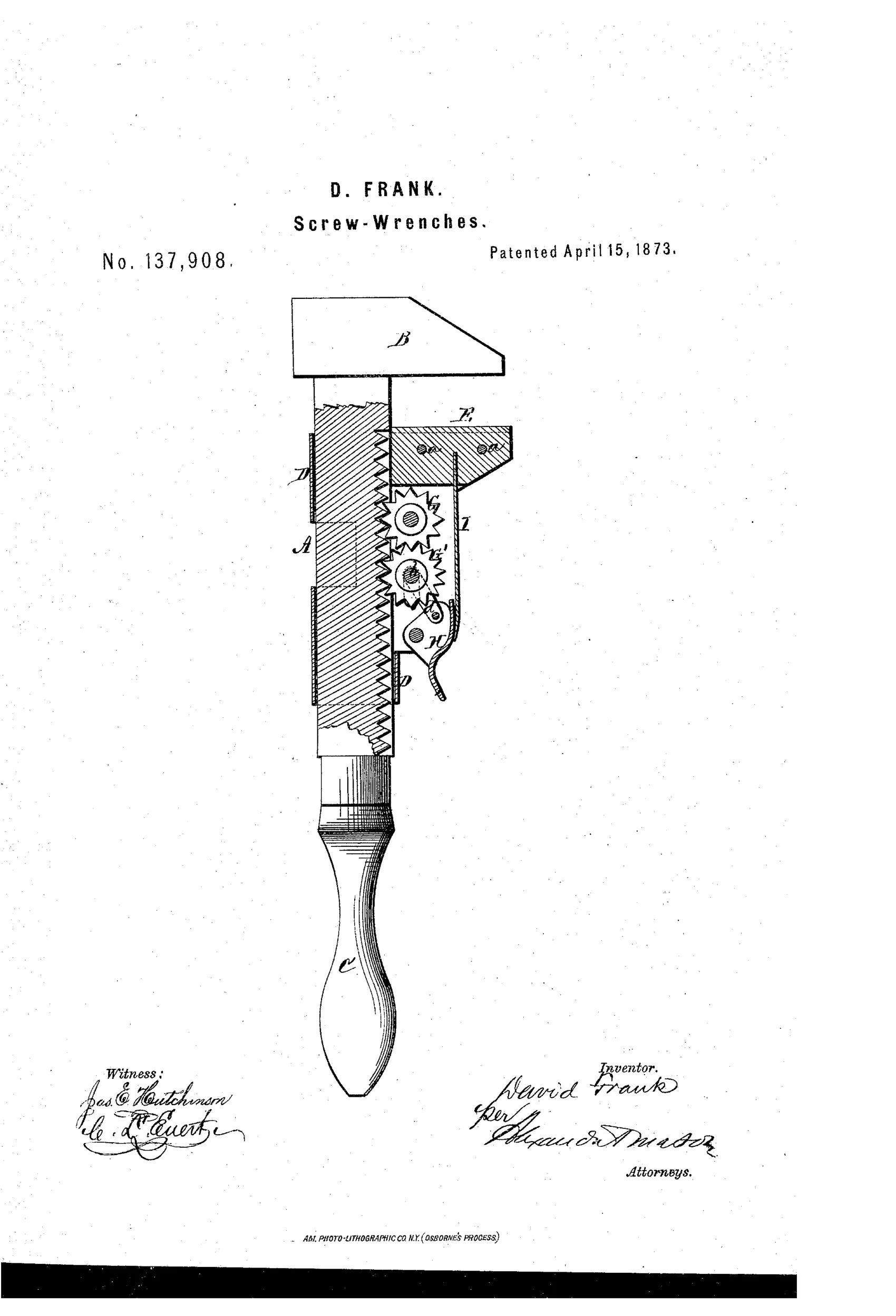
Monkey wrench with gear-locked movable jaw
⚙ How it works
The wrench has a toothed shank with a fixed jaw and a sliding frame carrying a movable jaw. A stationary pinion gear meshes with teeth on the shank, and a second movable pinion mounted on pivoted arms meshes with the first pinion, locking the sliding frame in place. Pressing a thumb-lever pivots the arms to disengage the movable pinion, allowing the jaw to slide freely, while a spring re-engages the gears once the lever is released to lock the jaw at the new position.
⚙ What was claimed
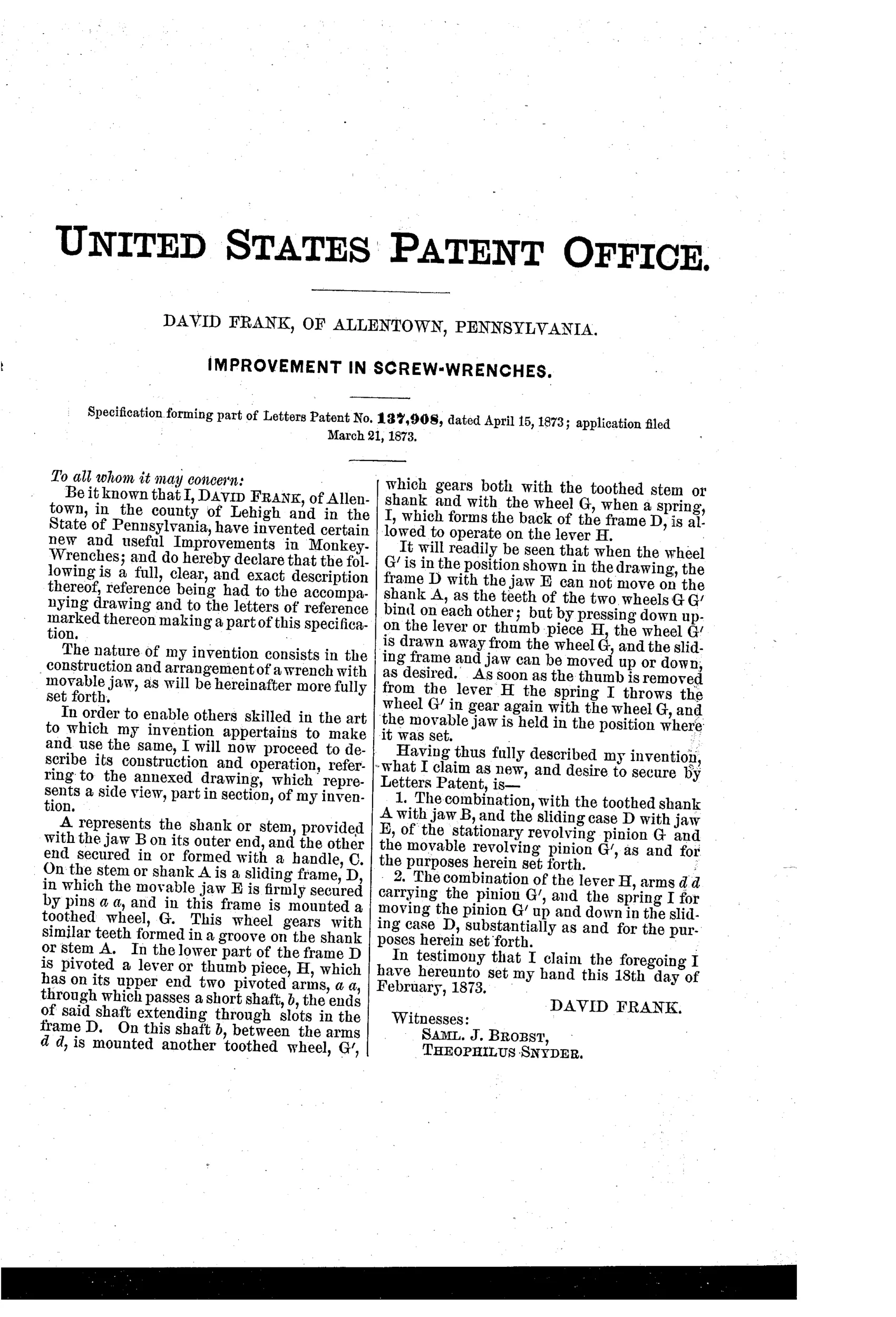
“The combination, with the toothed shank A with jaw B, and the sliding case D with jaw E, of the stationary revolving pinion G and the movable revolving pinion G′, as and for the purposes herein set forth.”
In plain English: A wrench where a fixed gear and a movable gear work together on a toothed shank to lock and release the sliding jaw.
⚙ In the inventor’s words
“It will readily be seen that when the wheel G′ is in the position shown in the drawing, the frame D with the jaw E can not move on the shank A, as the teeth of the two wheels G G′ bind on each other; but by pressing down upon the lever or thumb piece H, the wheel G′ is drawn away from the wheel G, and the sliding frame and jaw can be moved up or down, as desired.”— David Frank, from the specification
Fate unknown
No production wrench matching this gear-lock mechanism is catalogued in DATAMP or maker records; a marked specimen would settle it.
⚙ Commentary
David Frank's answer to the quick-adjust problem is a gear jam. The shank carries rack teeth, and a stationary pinion meshes with them as the sliding frame moves. That pinion alone would just spin. The trick is the second pinion, mounted on pivoted arms, that meshes with the first: with both engaged, neither can turn, the rack is locked, and the jaw stays put. Press the thumb-lever, the second pinion swings clear, the first pinion is free to rotate, and the jaw slides anywhere on the shank. A spring snaps the lock back the instant you let go. It is one-hand adjustment in 1873, decades before the mechanism collectors usually think of as the quick-adjust era.
The weak point is visible in the drawing if you look at the two little gears above the thumb-piece: all the wrenching load funnels through the tooth contact between two small pinions and a pivoted arm. A hard pull on a stubborn nut wants to force those teeth past each other or spring the arms. Coes-style screw adjustment is slower but puts the load on a broad threaded engagement; Frank trades that robustness for speed.
As a chapter in the category's story, this is an early and genuinely inventive entry in the crowd chasing instant adjustment — clever on paper, questionable under torque, and all the more interesting for it.
Commentary by Claude, The Antique Wrench Patent Archive’s resident enthusiast