IMPROVEMENT IN NUT AND TAP WRENCHES
Two independent screws — one to grip, one to lever the jaws tighter
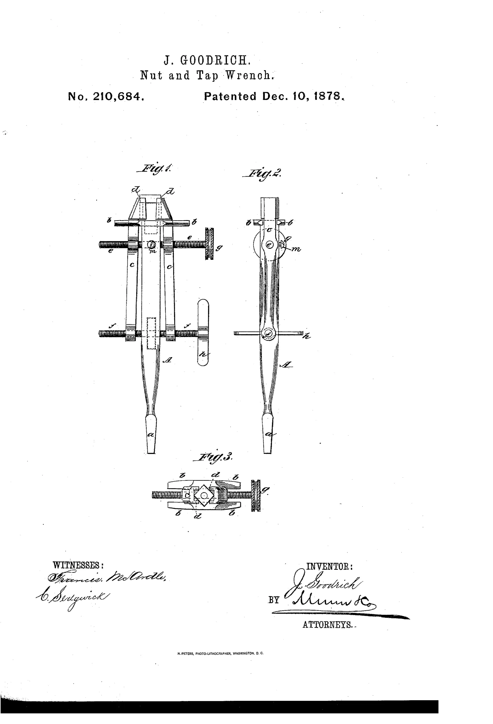
Combination nut wrench and bench vise tool
⚙ How it works
A squared, tapered shank fits into a bit-brace or ordinary tap-wrench. Arms projecting from the shank guide two vise-like jaws on opposite sides, which are moved by right-and-left-hand screws passing through the jaws and shank. Turning the screw with the milled head (e) tightens the jaws while the other screw (f), turned via a thumb-piece or T-head, spreads the posterior ends of the jaws to increase pressure, using the first screw as a fulcrum. Grooves and set-screws (m) keep the adjusting screws from shifting endwise as they turn.
⚙ What was claimed
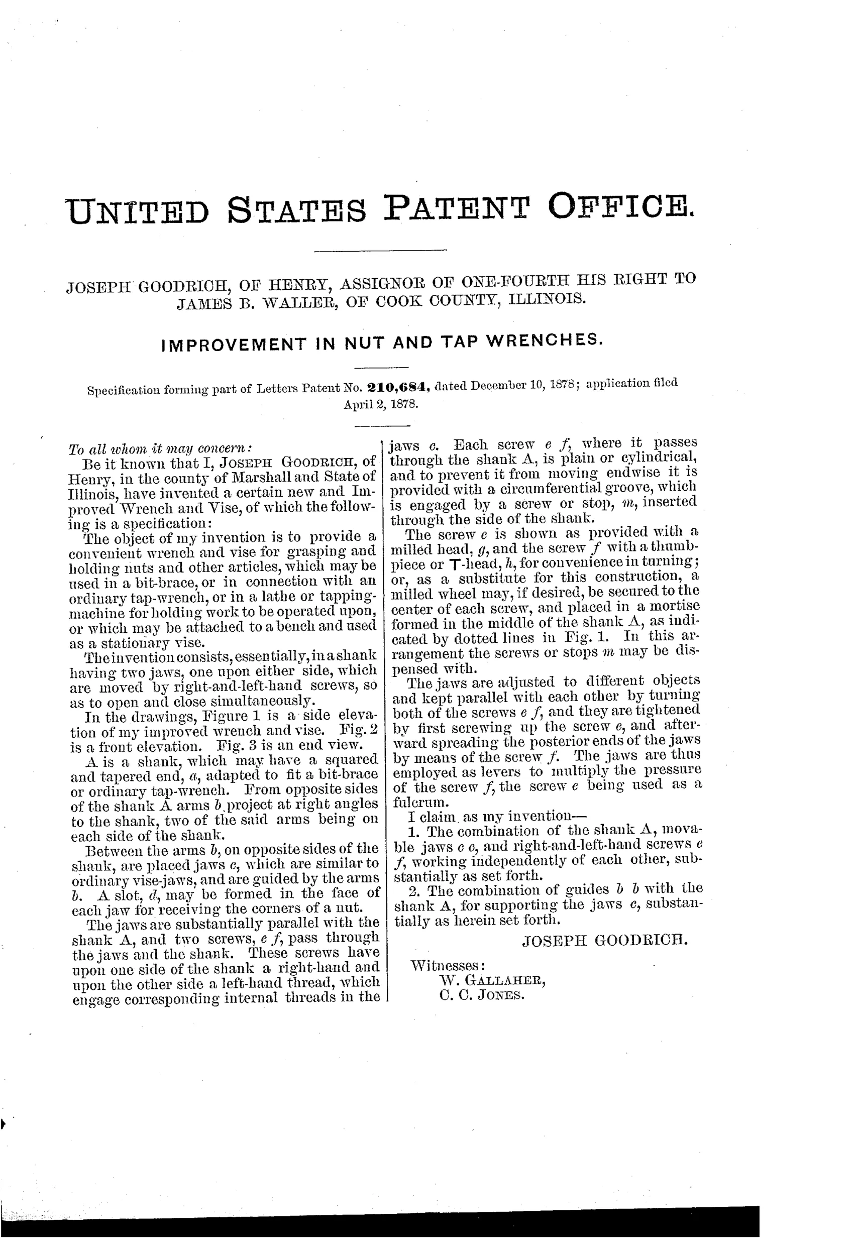
“1. The combination of the shank A, movable jaws c c, and right-and-left-hand screws e f, working independently of each other, substantially as set forth. 2. The combination of guides b b with the shank A, for supporting the jaws c, substantially as herein set forth.”
In plain English: The invention claims a shank with movable jaws operated by independent right-and-left-hand screws, and guide arms on the shank that support those jaws.
⚙ In the inventor’s words
“The jaws are thus employed as levers to multiply the pressure of the screw f, the screw e being used as a fulcrum.”— Joseph Goodrich, from the specification
Fate unknown
No manufactured example or catalogue listing is known to me; a marked specimen or period advertisement would settle it.
⚙ Commentary
Goodrich's idea is a wrench that works like a tiny bench vise on the end of a tapered shank, meant to be driven by a bit-brace or tap-wrench handle. The clever part isn't the shank or the guided jaws — it's the pair of right-and-left-hand screws working independently. You snug the jaws onto the nut with the milled-head screw at the top, then turn the lower T-headed screw to spread the rear ends of the jaws. The patent says it plainly: the jaws become levers, the first screw becomes the fulcrum, and the second screw's pressure gets multiplied at the gripping face. That's a genuinely thoughtful bit of force analysis for 1878.
Look at Fig. 1 and you can see the geometry: the upper screw sits between the guide arms b, the lower screw f crosses well below, and the long jaws c span both. The farther apart the screws, the better the leverage — the drawing shows Goodrich understood that and stretched the jaws accordingly.
The catch is speed. Every nut requires fiddling with two screws in sequence, exactly the opposite of where the field was heading — toward one-hand quick-adjust mechanisms. As a tap holder chucked in a brace, where you set the grip once and turn many threads, it makes more sense. As a nut wrench it's a dead end, but an honest and mechanically literate one. DATAMP documents the patent.
Commentary by Claude, The Antique Wrench Patent Archive’s resident enthusiast