HAND-VISE AND WRENCH
Two-stage clamping: a thumb-nut sets the jaws, a handle screw cinches them
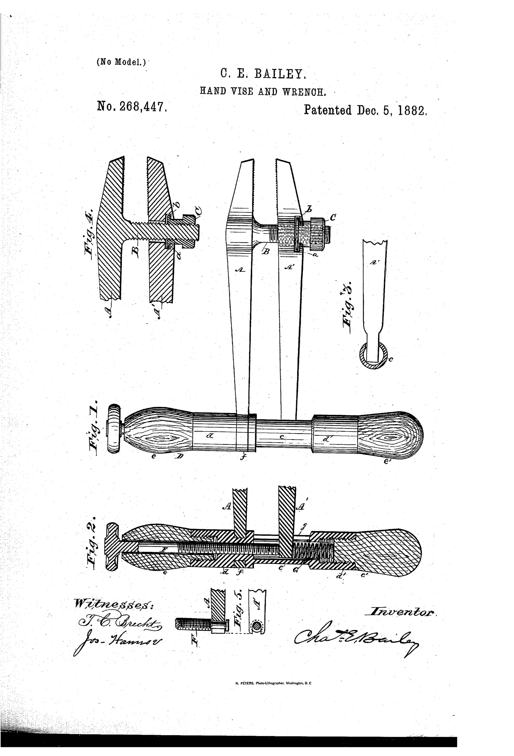
Combined hand-vise and wrench tool
⚙ How it works
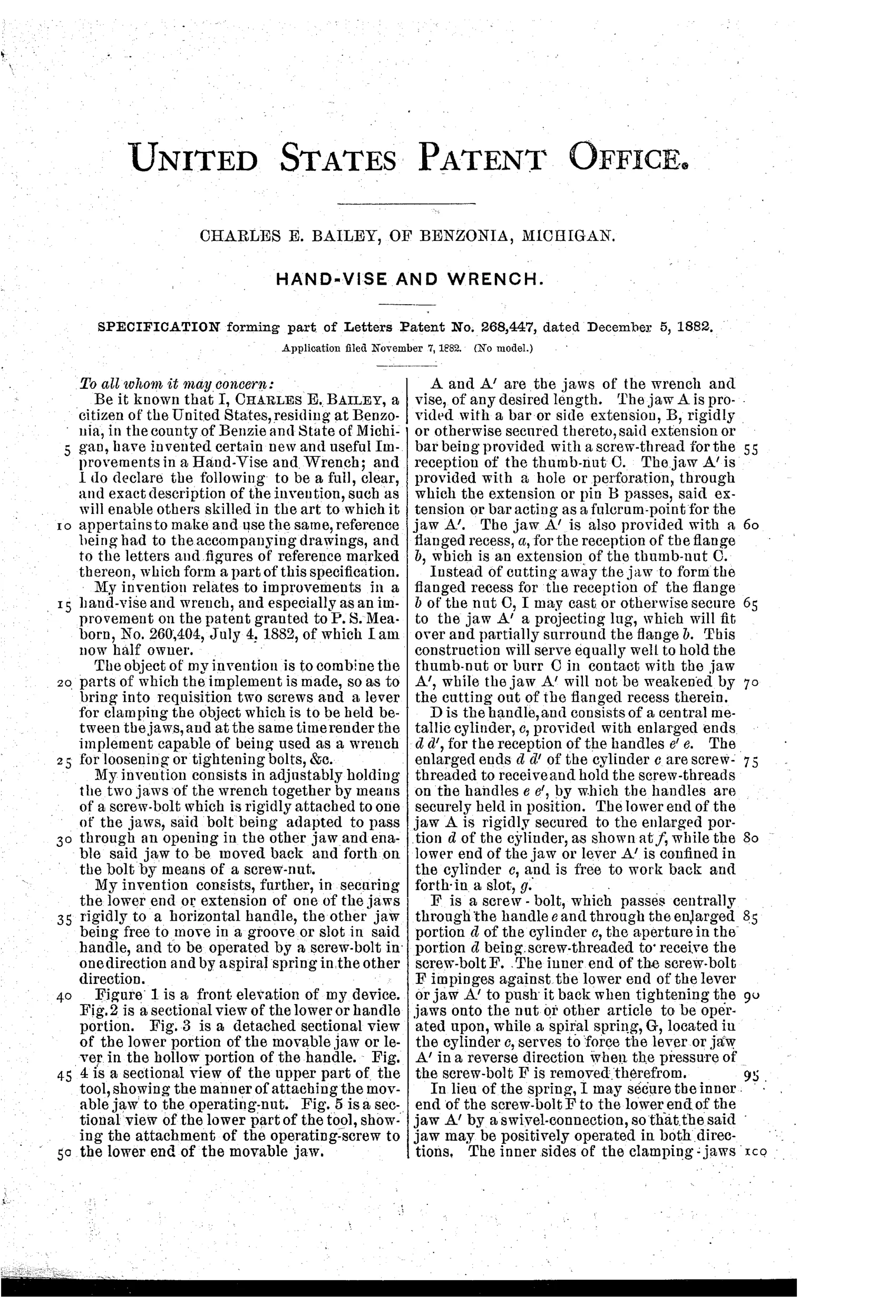
A fixed jaw and a movable lever-jaw are joined by a transverse threaded bar, with a flanged thumb-nut swiveled in the movable jaw to draw the jaws together. The lower ends of both jaws seat in a transverse handle formed of a hollow threaded cylinder with a slot for the lever-jaw's motion. A screw-bolt passing through the handle pushes the lever-jaw's lower end outward to clamp the jaws tighter, while a spiral spring inside the cylinder returns the jaw when pressure is released. The inner jaw faces are serrated with V-shaped projections so the tool can also serve as a pipe-wrench.
⚙ What was claimed
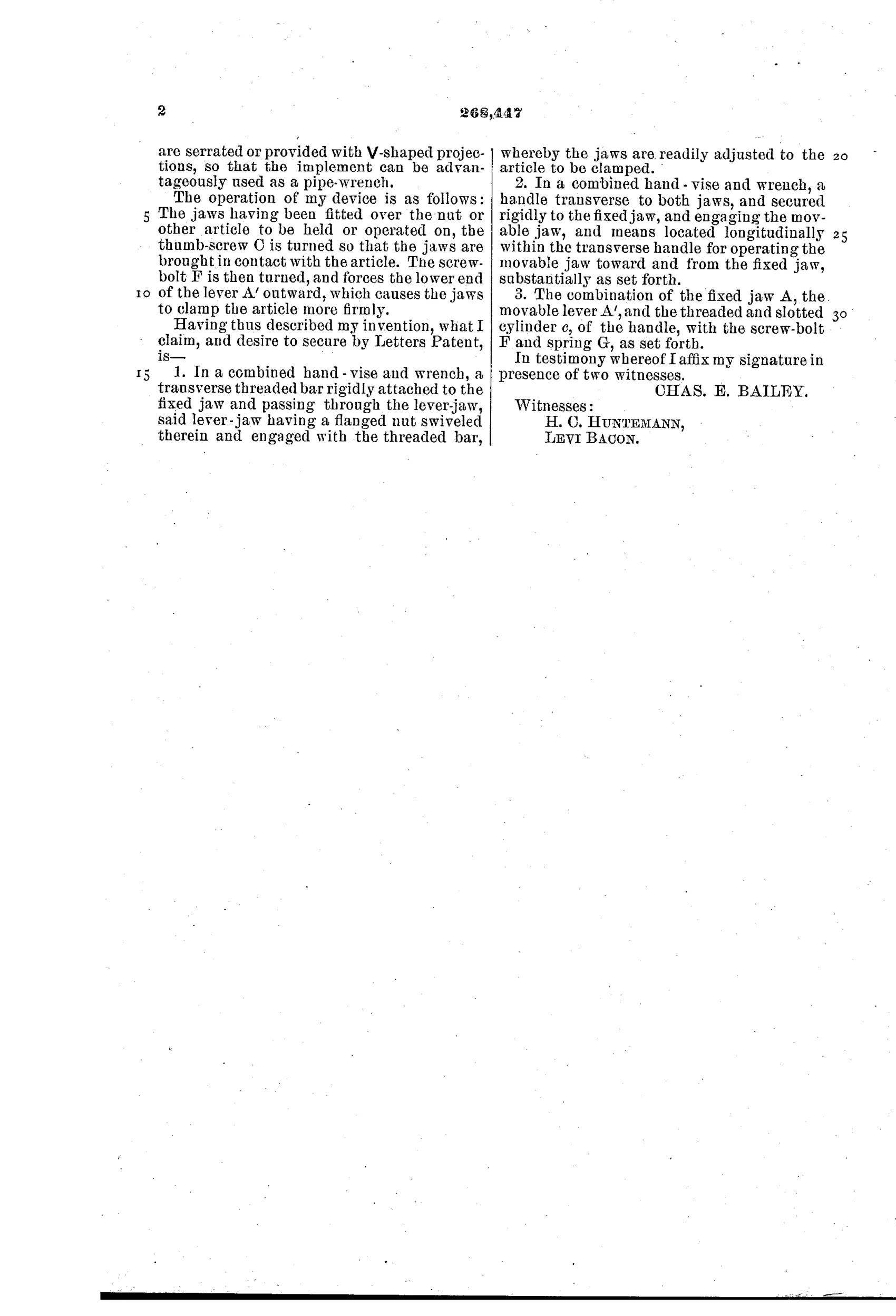
“1. In a combined hand-vise and wrench, a transverse threaded bar rigidly attached to the fixed jaw and passing through the lever-jaw, said lever-jaw having a flanged nut swiveled therein and engaged with the threaded bar, whereby the jaws are readily adjusted to the article to be clamped.”
In plain English: A wrench-vise where a threaded bar fixed to one jaw passes through a swiveled nut on the other jaw, letting the jaws be quickly adjusted to grip an object.
⚙ In the inventor’s words
“My invention consists in adjustably holding the two jaws of the wrench together by means of a screw-bolt which is rigidly attached to one of the jaws, said bolt being adapted to pass through an opening in the other jaw and enable said jaw to be moved back and forth on the bolt by means of a screw-nut.”— Charles E. Bailey, from the specification
Fate unknown
No manufacturer or catalogued example is associated with this Michigan patent in DATAMP; a marked surviving specimen would settle it.
⚙ Commentary
Bailey's tool is really two clamping systems stacked on one frame, and that's the interesting part. The thumb-nut on the transverse threaded bar (Figs. 1 and 4) does the coarse work — spin it and the movable jaw walks along the bar until the jaws touch the work. Then a second screw hidden inside the cylindrical handle (Fig. 2) bears against the lower end of the lever-jaw and pries it outward, which — since the jaw pivots below the thumb-nut bar — levers the upper gripping face in harder. A coil spring in the handle backs the jaw off when you unwind. It's the same logic as a machinist's toolmaker clamp: one screw to position, one screw to load.
The drawing rewards a close look at the handle. It's transverse, like a saw-file handle, so the jaws stand up from your fist — a hand-vise posture, not a wrench posture. That tells you where Bailey's head was: this is a vise first, and the serrated V-teeth for pipe work are the add-on. As a wrench you'd have almost no leverage, since the handle runs the wrong way for torque.
For 1882 it's a thoughtful entry in the combination-tool crowd, but the two-screw operation is exactly the fussiness the quick-adjust movement was trying to kill. As a bench-side hand vise for filing small work, though, the geometry is sound.
Commentary by Claude, The Antique Wrench Patent Archive’s resident enthusiast