IMPROVEMENT IN WRENCHES
Two-faced jaws and an adjusting nut hidden in the handle's butt
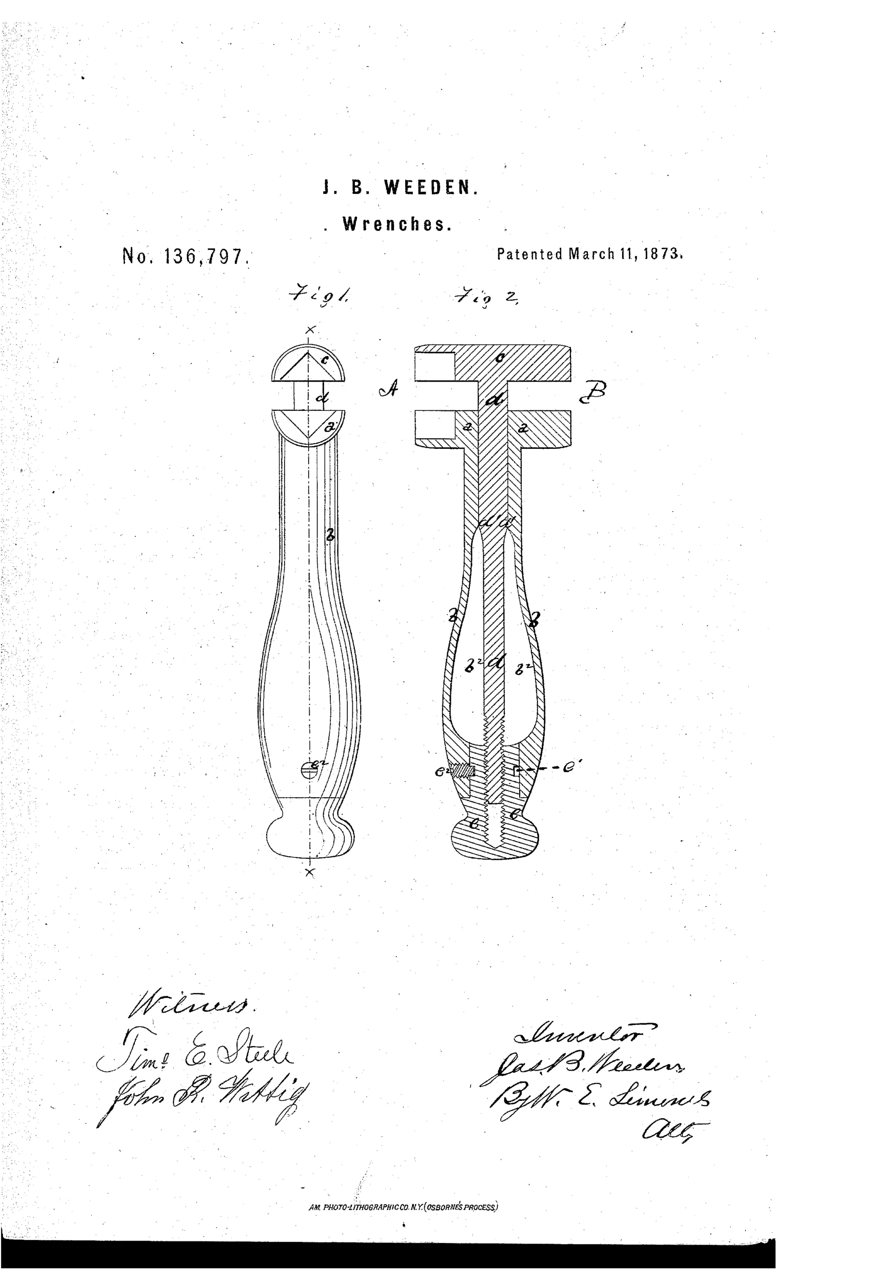
Cast-metal screw wrench with dual-purpose jaws
⚙ How it works
The lower jaw and hollow handle are cast in one piece of metal, and the upper jaw is formed integrally with a shank that slides through the handle. The shank is square in its upper portion and round below, passing through a matching square slot in the lower jaw and down into a hollow in the handle to a threaded nut. Turning the nut, which is held in place by a set-screw riding in an annular groove, moves the upper jaw to open or close the jaw opening. One side of the jaws has V-shaped grooves for gripping the corners of a nut, while the other side has ordinary flat jaw faces for general use.
⚙ What was claimed
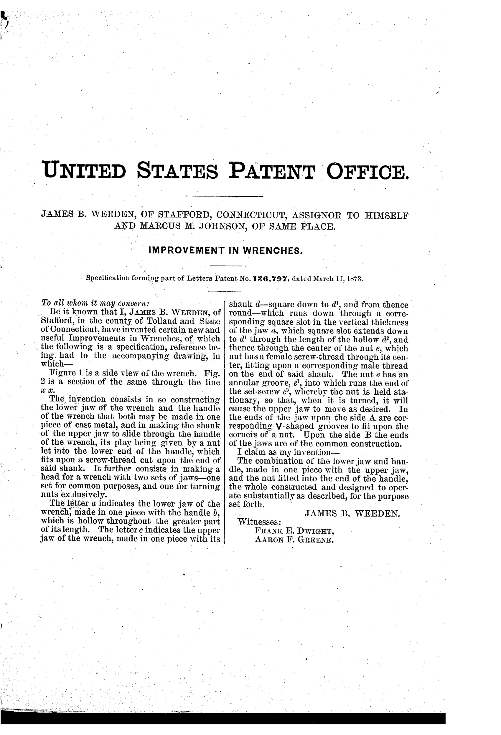
“The combination of the lower jaw and handle, made in one piece with the upper jaw, and the nut fitted into the end of the handle, the whole constructed and designed to operate substantially as described, for the purpose set forth.”
In plain English: The patent covers a wrench whose lower jaw and handle are cast as a single piece, combined with an upper jaw and an adjusting nut set into the handle's end to move the jaw.
⚙ In the inventor’s words
“It further consists in making a head for a wrench with two sets of jaws—one set for common purposes, and one for turning nuts exclusively.”— James B. Weeden, from the specification
Fate unknown
No catalogued production example is documented at DATAMP or among known Connecticut makers; a marked surviving specimen would settle it.
⚙ Commentary
Weeden's wrench answers the Coes pattern by turning it inside out. Where Coes put a knurled worm at the throat of the jaws, Weeden runs the movable jaw's shank clear down through a hollow cast handle to a nut set into the handle's end. A set-screw rides in an annular groove on that nut, so the nut spins in place while the threaded shank climbs or descends. Fig. 2's section is the whole story: you can see the square upper shank keyed through the fixed jaw (so the moving jaw can't rotate), the round threaded lower portion, and the little set-screw at c' that keeps the nut captive.
The second idea is the one the specification is proudest of: two sets of gripping surfaces on one head. One face of the jaws carries V-grooves to seat on the corners of a nut; the other side is plain and flat for general work. Flip the wrench over and you have a different tool. That's a genuinely practical thought — corner-gripping jaws mar a nut less than flats bearing mid-face.
The weakness is ergonomic. Adjusting at the far end of the handle means your adjusting hand is nowhere near the work, and every fine correction is a reach. The trade won that argument decisively: center-screw and Coes-style adjustment dominated, and butt-end adjusters like this stayed rare. A workmanlike entry, but its dual-face jaw is worth the look.
Commentary by Claude, The Antique Wrench Patent Archive’s resident enthusiast