IMPROVEMENT IN WRENCHES
Working force locks the jaw; a tap on the handle unlocks it
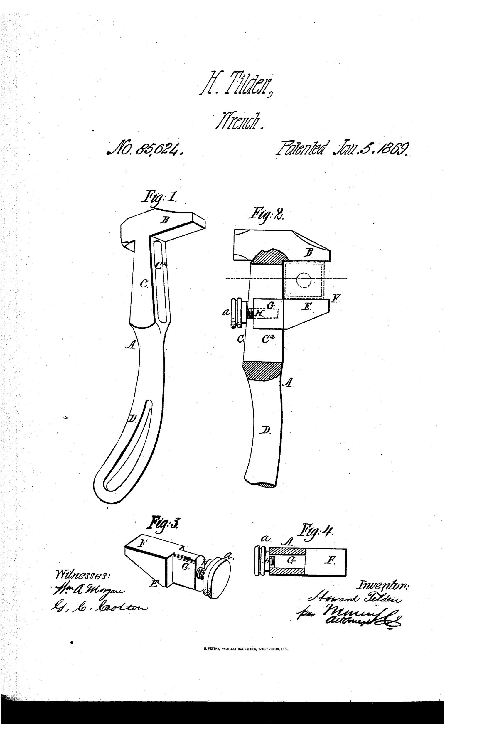
Adjustable monkey wrench with wedge-locking movable jaw
⚙ How it works
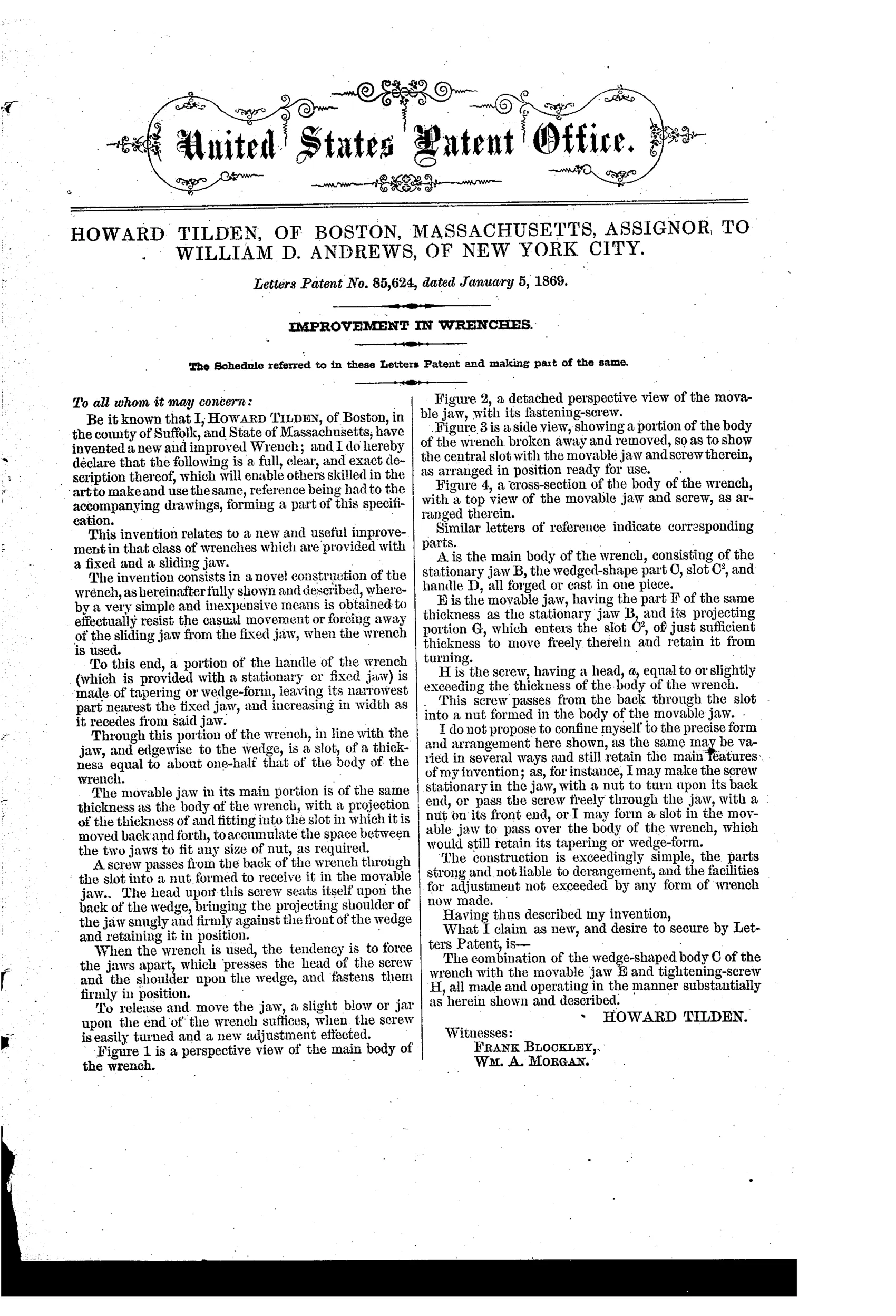
The wrench body has a tapering, wedge-shaped section that narrows nearest the fixed jaw and widens toward the handle, with a lengthwise slot cut through this wedge. The movable jaw has a projecting tongue that fits into this slot and slides back and forth to fit different nut sizes. A screw passes from the back of the wrench through the slot into a nut formed in the movable jaw; when the wrench is used, the force of turning presses the screw head and jaw shoulder against the wedge, locking the jaw firmly in place. A slight blow or jar on the end of the wrench releases the jaw so the screw can be turned and a new adjustment made.
⚙ What was claimed
“The combination of the wedge-shaped body C of the wrench with the movable jaw E and tightening-screw H, all made and operating in the manner substantially as herein shown and described.”
In plain English: The claim covers the combination of the wedge-shaped wrench body, the movable jaw, and the tightening screw working together as described.
⚙ In the inventor’s words
“When the wrench is used, the tendency is to force the jaws apart, which presses the head of the screw and the shoulder upon the wedge, and fastens them firmly in position.”— Howard Tilden, from the specification
Fate unknown
The assignment to Andrews hints at commercial intent, but no marked example is documented in DATAMP; a surviving specimen would settle it.
⚙ Commentary
Tilden's idea inverts the usual worry about adjustable wrenches. In a Coes-style screw wrench, the load on the jaws is always trying to back the mechanism off, so the wrench must be built stout enough to resist it. Here the load is recruited as the lock: the body is a wedge, thick at the handle end and thin at the fixed jaw, with a slot running through it. The movable jaw straddles the wedge, tongue in the slot, screw head bearing on the back. Pull on a nut and the jaw is pressed harder against the taper — the harder you wrench, the tighter it grips. To readjust, you give the handle end a smart blow, the wedge releases, and the screw slides to the new setting.
The drawing makes the geometry clear: Fig. 2 shows the section with the taper hatched, and Fig. 3 shows the little jaw-and-screw assembly detached like a saddle. Notice the screw isn't doing the holding — it's just a keeper and a fine-adjust. That's the clever part, and also the questionable part: friction wedges that self-tighten also self-jam, and 'a slight blow or jar' is doing a lot of work in the specification. Grease, wear on the taper, or a rounded slot edge would all change the release behavior.
It sits in the crowd chasing quick, one-hand adjustment before the 1890s made that a fashion — an early, honest attempt with an assignee already lined up in New York, which suggests someone thought it saleable.
Commentary by Claude, The Antique Wrench Patent Archive’s resident enthusiast