IMPROVEMENT IN CARRIAGE-WHEEL WRENCHES.
Clamp the hub, clamp the nut, then let the wheel do the wrenching
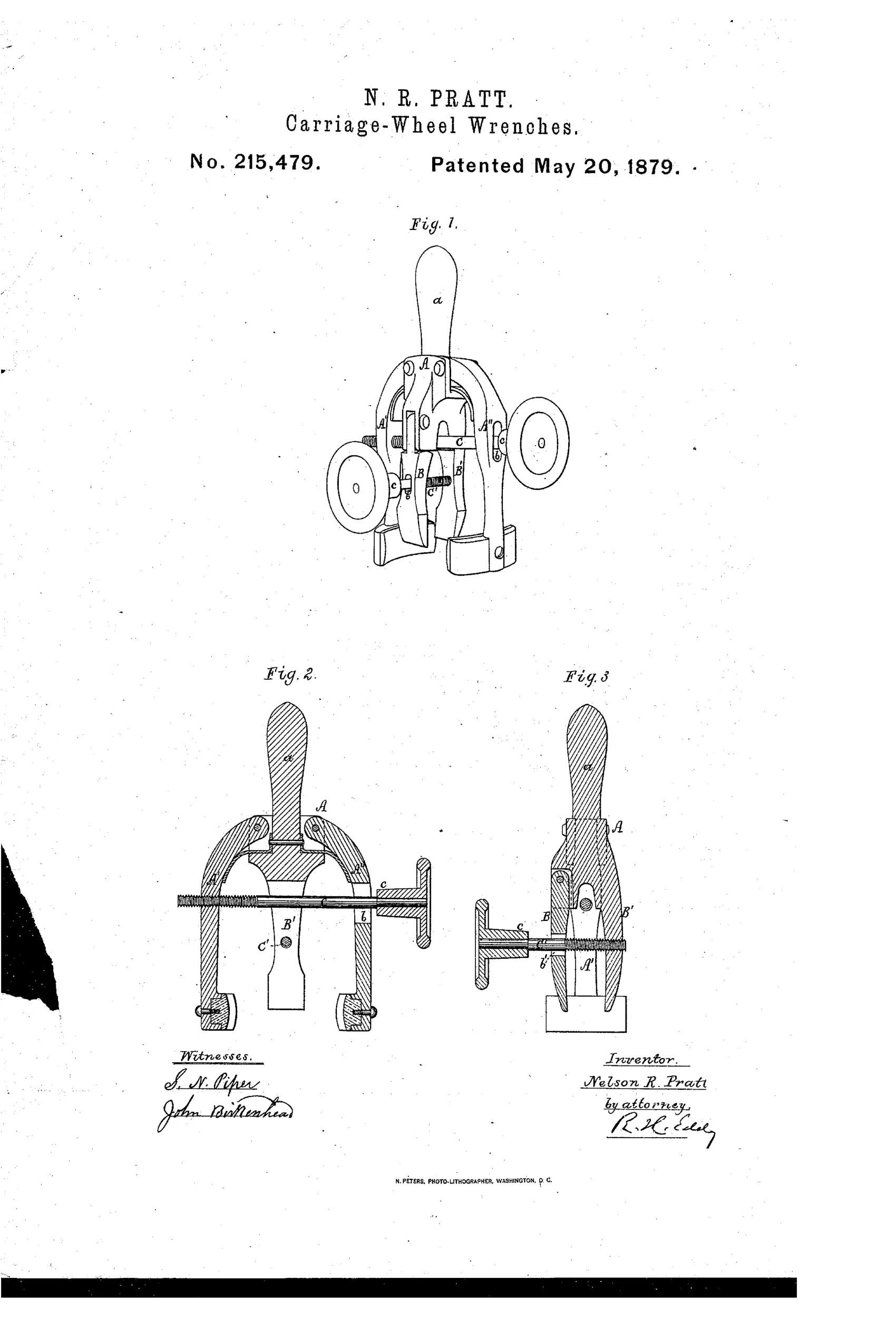
A wheel-hub-and-axle-nut wrench
⚙ How it works
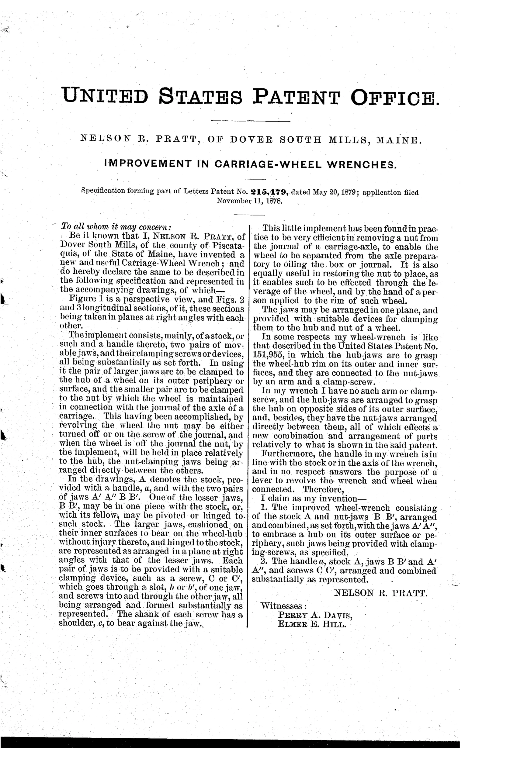
The implement consists of a stock A with a handle a, and two pairs of movable jaws set at right angles to each other. The larger jaws, A' and A", are hinged to the stock and clamp onto the outer periphery of a wheel hub, with cushioned inner surfaces to avoid marring it. The smaller jaws, B and B', are arranged directly between the larger jaws and clamp onto the axle nut. Each pair of jaws is tightened by a clamping screw (C or C') that passes through a slot in one jaw and threads into the other, with a shouldered shank bearing against the jaw; revolving the wheel then turns the nut on or off the journal.
⚙ What was claimed
“1. The improved wheel-wrench consisting of the stock A and nut-jaws B B', arranged and combined, as set forth, with the jaws A' A", to embrace a hub on its outer surface or periphery, such jaws being provided with clamping-screws, as specified.”
In plain English: The wrench combines a stock with a pair of screw-clamped nut jaws set between a pair of screw-clamped hub jaws that grip the wheel hub's outer surface.
⚙ In the inventor’s words
“This little implement has been found in practice to be very efficient in removing a nut from the journal of a carriage-axle, to enable the wheel to be separated from the axle preparatory to oiling the box or journal.”— Nelson R. Pratt, from the specification
Fate unknown
No marked example or catalogue listing is documented in DATAMP or the collecting literature; a surviving specimen would settle it.
⚙ Commentary
Pratt's idea sidesteps the usual awkwardness of axle-nut work. Instead of bracing the wheel with one hand and heaving a wrench with the other, his tool grabs both parts at once: the outer jaws A' and A" clamp around the hub's periphery (cushioned, so the paint and wood survive), while the smaller jaws B and B' seize the axle nut between them. With everything locked together, you simply revolve the wheel itself — a lever several feet in diameter — and the nut spins off. That's the clever part: the wheel becomes the wrench handle.
The drawing rewards a second look. Fig. 1 shows the X-shaped body with the two jaw pairs set at right angles, and the knurled clamping screws C and C' with their shouldered shanks — one screw per jaw pair, each passing through a slot in one jaw and threading into its mate. Figs. 2 and 3 section the tool both ways so you can see how the nut jaws nest between the hub jaws without fouling them.
The rub is speed. Two screw clamps to tighten and loosen at every wheel is slow compared with the simple square-socket hub wrenches that shipped with every buggy, and those cost pennies. Pratt's device is more considerate of the wheel and easier on the arms, but the trade was chasing cheap and fast. This sits in the carriage-wrench story as a thoughtful cul-de-sac: mechanically sound, economically outflanked.
Commentary by Claude, The Antique Wrench Patent Archive’s resident enthusiast