WRENCH.
A wrench chucked in a bit brace, spinning nuts like an auger bores holes
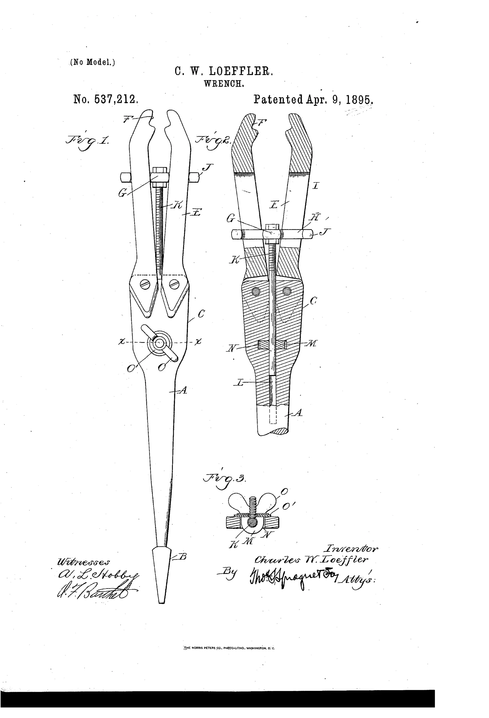
Adjustable wrench designed for use as a brace bit
⚙ How it works
The wrench has a shank with a squared end to fit into a brace socket, with bifurcated jaws pivoted at the opposite end. A spreader head with laterally extending arms passes through slots in the jaws, and cross-bars on the arms engage the outer face of the jaws to spread or close them. A rod secured to the spreader head slides through an aperture in the shank and is clamped in position by a wing nut on a screw eye, allowing the jaw spread to be locked once adjusted to fit a nut. Turning the brace then tightens or loosens the engaged nut.
⚙ What was claimed
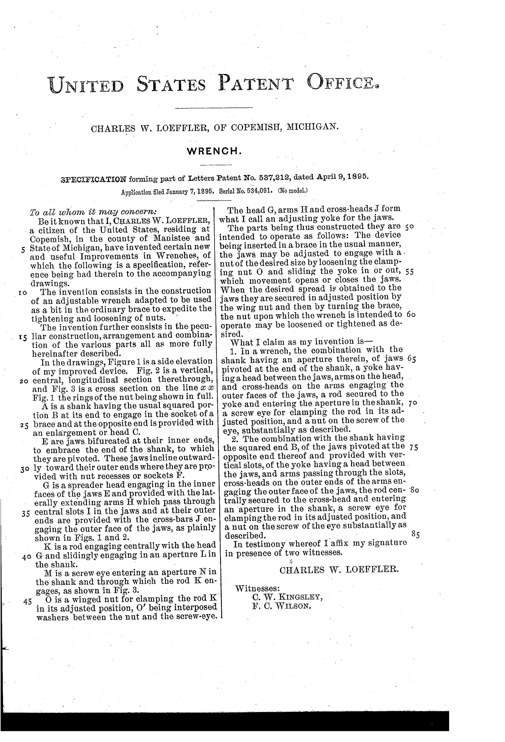
“In a wrench, the combination with the shank having an aperture therein, of jaws pivoted at the end of the shank, a yoke having a head between the jaws, arms on the head, and cross-heads on the arms engaging the outer faces of the jaws, a rod secured to the yoke and entering the aperture in the shank, a screw eye for clamping the rod in its adjusted position, and a nut on the screw of the eye, substantially as described.”
In plain English: The wrench combines a slotted shank, pivoted jaws, a spreading yoke with arms and cross-heads that engage the jaws, and a lockable rod-and-nut mechanism to fix the jaw spread.
⚙ In the inventor’s words
“The device being inserted in a brace in the usual manner, the jaws may be adjusted to engage with a nut of the desired size by loosening the clamping nut O and sliding the yoke in or out, which movement opens or closes the jaws.”— Charles W. Loeffler, from the specification
Fate unknown
No manufacturer or catalogued example is associated with this patent in DATAMP or the collector literature; a marked specimen would settle it.
⚙ Commentary
Most adjustable wrenches of the 1890s fight over how fast you can set the jaw with one hand. Loeffler sidesteps the whole contest: his wrench has no handle at all. The tapered square end at the bottom of Fig. 1 goes into an ordinary carpenter's bit brace, and the brace does the turning. Set the jaws once to fit the nut, lock them with the wing nut, and crank — every sweep of the brace is a full revolution of the nut, no ratcheting, no repositioning on the flats. For a job with dozens of identical nuts, say assembling farm machinery, that's a genuinely appealing pitch.
The adjustment is the clever bit worth slowing down for. The jaws pivot at the top of the shank, and a yoke slides between them; its cross-arms bear on the outer faces of the jaws through slots, so pulling the yoke down wedges the jaws apart and pushing it up lets them close. A rod from the yoke runs down through the hollow shank and is pinched by a screw eye and wing nut — Fig. 3 shows that clamp in section. It's a friction lock, which is the design's weak joint: heavy torque on a stubborn nut is exactly when you don't want your jaw setting held by a thumb-tightened wing nut.
As brace-driven socket wrenches go, this is a niche corner of the field, and Loeffler of Copemish, Michigan left no maker's trail I know of. A thoughtful dead end, most likely — but the problem it solves was real.
Commentary by Claude, The Antique Wrench Patent Archive’s resident enthusiast