COMPOUND-ACTION MONKEY-WRENCH.
A monkey wrench with a ratcheting handle, sold on sparing the operator's elbow
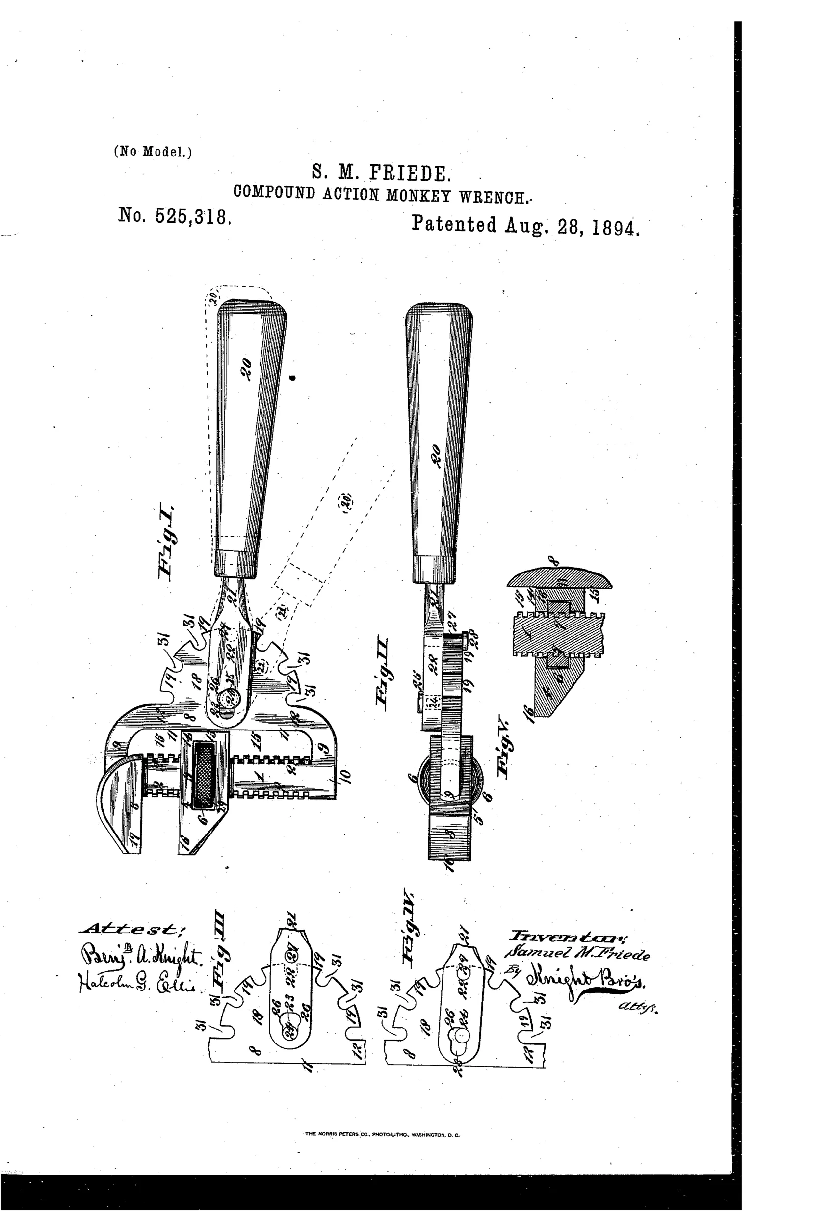
A ratcheting compound-action monkey wrench
⚙ How it works
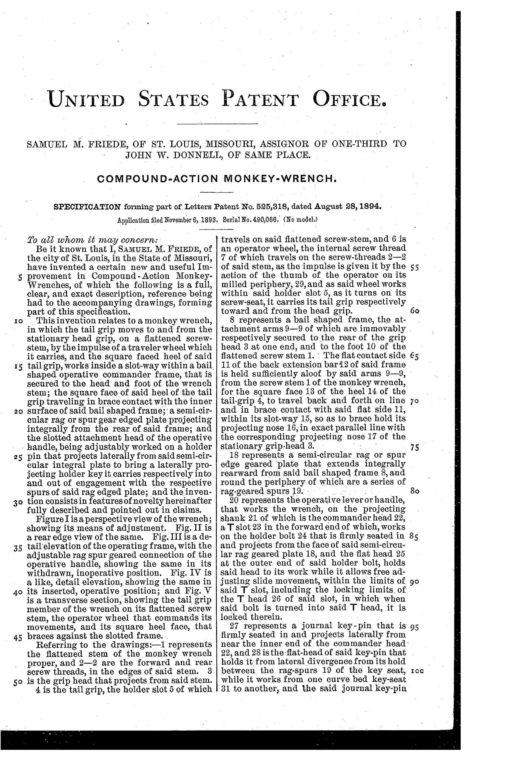
The wrench has a stationary grip-head and an adjustable tail-grip that travels on a flattened screw stem via a threaded operator wheel. A bail-shaped frame with an integral semi-circular rag-spur gear plate is fixed to the head and foot of the stem. The operative handle's commander head carries a key-pin that journals between curve-bed interspaces of the rag-spurs, and a T-slotted holder bolt locks the handle to the gear plate. By disengaging and re-seating the key-pin at successive spur positions, the operator can renew leverage and complete a full turn in cramped spaces without releasing the wrench's grip on the work.
⚙ What was claimed
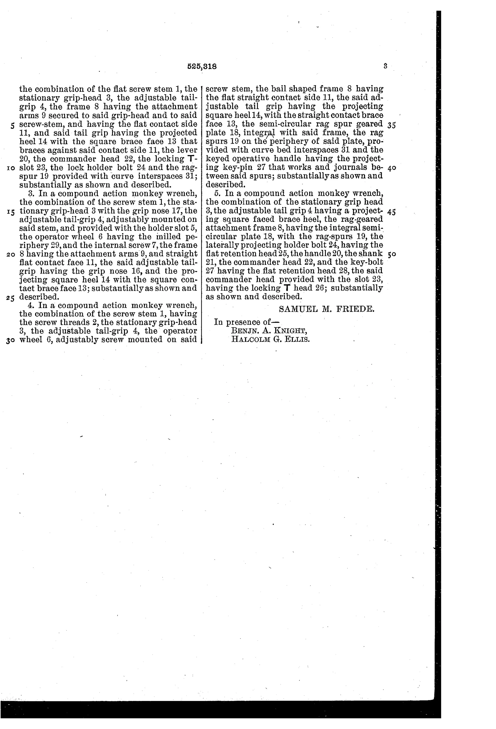
“In a compound action monkey wrench, the combination of the stationary clamping grip-head or jaw 3, the screw adjustable clamping tail-grip or jaw 4, having the rear projected heel 14 and square bracing face 13, the rag-spur attachment frame, against which said square faced heel braces, the rag-spur plate 18, the projecting holder bolt 24, the rag-spurs 19, provided with curve bed interspaces 31 the handle 20 with its commander head 22, provided with the locking T-slot 23, and the key-pin 27, that works and journals in said curve bed interspaces 31 between said rag-spur gear, and adjusts the hold of the wrench; substantially as shown and described.”
In plain English: The wrench combines a fixed jaw, a screw-adjustable sliding jaw braced by a square heel against a geared frame, and a handle whose locking head and key-pin engage successive gear teeth to reset and renew turning leverage without losing grip.
⚙ In the inventor’s words
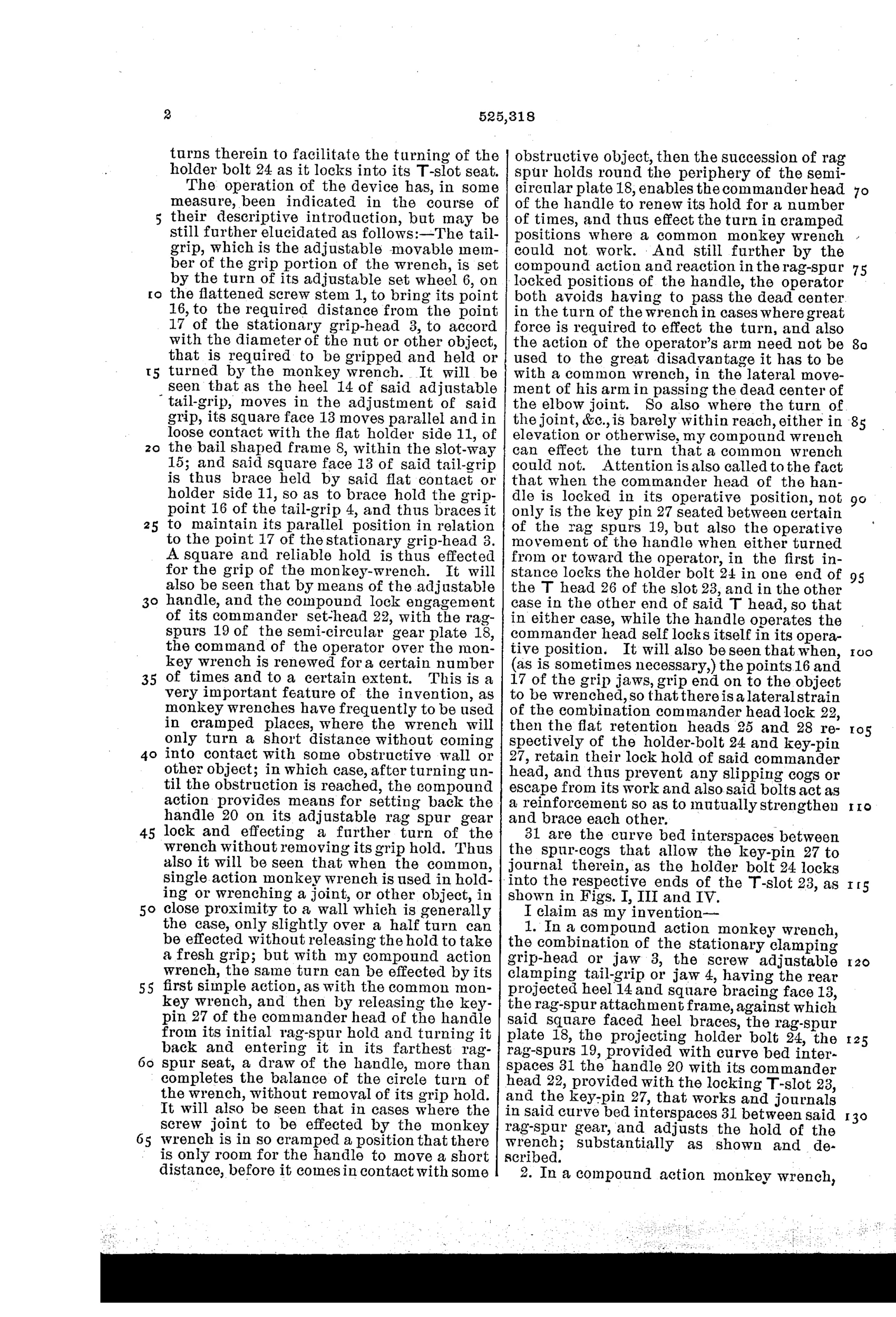
“And still further by the compound action and reaction in the rag-spur locked positions of the handle, the operator both avoids having to pass the dead center in the turn of the wrench in cases where great force is required to effect the turn, and also the action of the operator's arm need not be used to the great disadvantage it has to be with a common wrench, in the lateral movement of his arm in passing the dead center of the elbow joint.”— Samuel M. Friede, from the specification
Fate unknown
No catalogued or surviving example is documented; a marked specimen or a Donnell trade advertisement would settle it.
⚙ Commentary
Friede's idea is to graft a ratchet onto a monkey wrench without touching the jaws. The wrench body — fixed head, screw-adjusted tail-grip — is conventional. What's new is the semicircular 'rag-spur' gear plate fixed to the frame, and a separate handle whose head carries a key-pin. Seat the pin between two spur teeth, lock it with the T-slotted holder bolt, pull; then lift, re-seat one tooth over, and pull again. The jaws never release the nut, so in a cramped corner you can walk a fastener around in short strokes instead of re-fitting the wrench a dozen times.
The drawing rewards a close look. Fig. I shows the handle in dashed lines swung to an alternate position — the whole point of the patent in one ghost image. Figs. III and IV show the commander head withdrawn and inserted, and Fig. V reveals the flattened screw stem that keeps the tail-grip from rotating while the square heel braces it against the geared frame, so ratcheting loads don't feed back into the adjustment screw. That heel-bracing detail is genuinely thoughtful; a plain monkey wrench would wrack its screw under this use.
Still, it's a lot of parts doing what a socket ratchet does more simply, and by 1894 the field's energy was flowing toward quick-adjust jaws, not compound handles. The specification's earnest passage about the 'dead center of the elbow joint' tells you Friede was solving a real ergonomic annoyance — with more machinery than the market would carry. DATAMP is the reference for the paper trail.
Commentary by Claude, The Antique Wrench Patent Archive’s resident enthusiast