IMPROVEMENT IN WRENCHES.
A hinged screw that swings clear: quick-release adjustment in 1870, from coal country
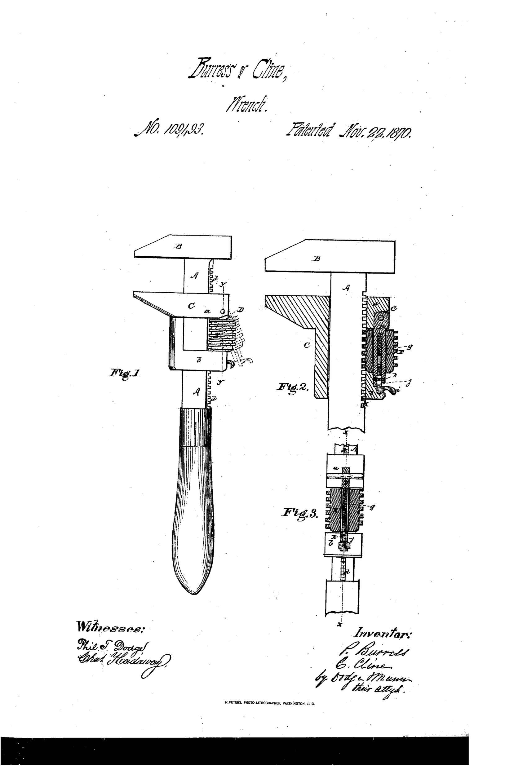
Adjustable rack-and-screw wrench with quick-release jaw
⚙ How it works
The wrench has a shank A with a toothed rack running its length and a fixed jaw B at one end. A movable jaw C clasps the shank with two arms and carries a pivoted bolt D holding a thumb-screw E, which engages the rack teeth to slide and tighten the jaw. A spring-loaded catch h with thumb-piece i locks the bolt closed against the rack, and pressing the thumb-piece releases the bolt so the jaw can be quickly slid to a new position without unscrewing the thumb-screw fully.
⚙ What was claimed
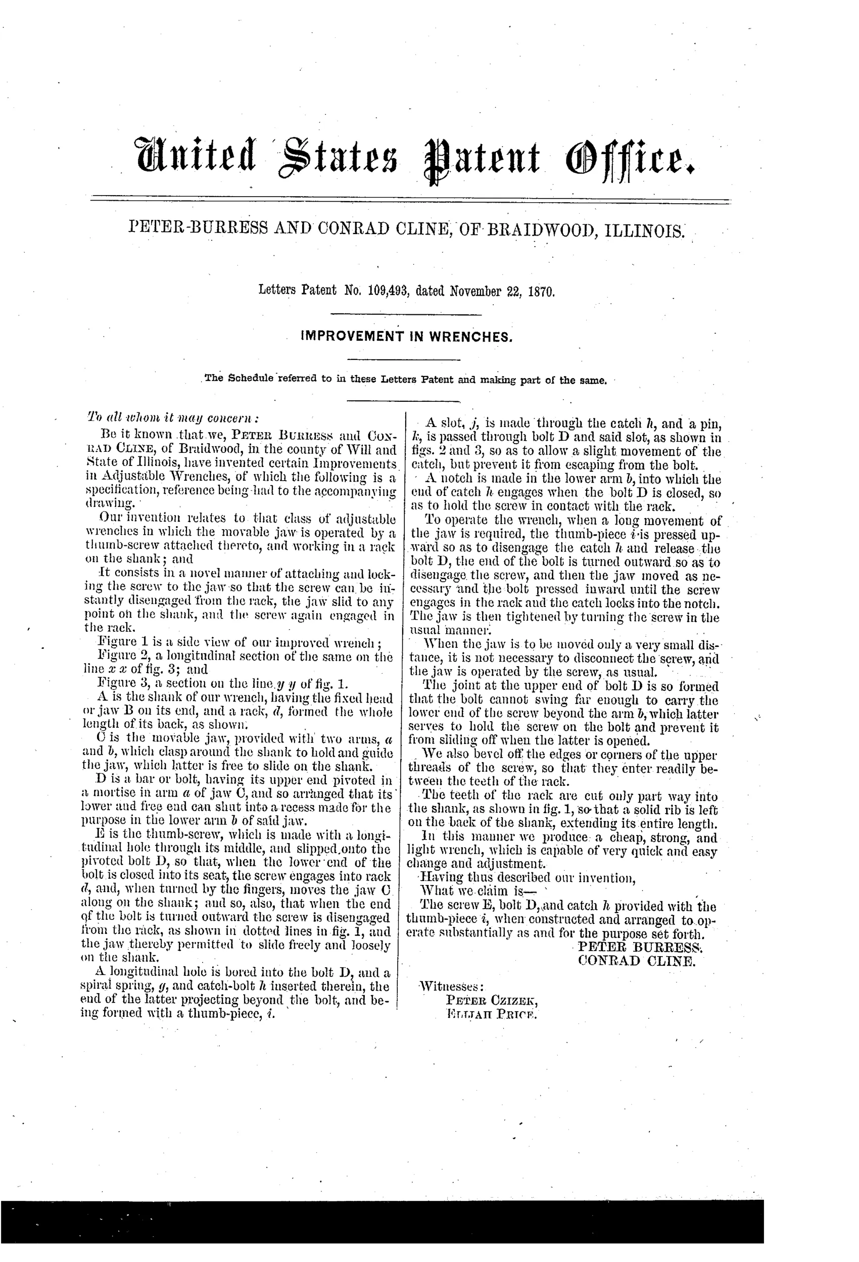
“The screw E, bolt D, and catch h provided with the thumb-piece i, when constructed and arranged to operate substantially as and for the purpose set forth.”
In plain English: The claim covers the specific combination of the adjusting screw, pivoted bolt, and spring catch with thumb-piece that lets the jaw be quickly released and relocked on the shank.
⚙ In the inventor’s words
“In this manner we produce a cheap, strong, and light wrench, which is capable of very quick and easy change and adjustment.”— Peter Burress and Conrad Cline, from the specification
Fate unknown
No manufactured example or catalogue listing is documented in DATAMP or the collector literature; a marked specimen would settle it.
⚙ Commentary
Burress and Cline attack the classic complaint against the screw wrench — that spinning a thumb-screw across a big jump in nut sizes takes forever — with a neat compromise. Their thumb-screw E doesn't drive the jaw through a fixed nut; it rides on a bolt D that is pivoted to the sliding jaw. A spring catch h with a thumb-piece i holds the bolt closed so the screw threads engage the rack teeth on the shank. Press the thumb-piece and the whole screw assembly hinges away from the rack, letting the jaw slide freely to a new position. Snap it back, and the screw is there for the fine adjustment. Coarse-plus-fine in one motion — that's the quick-adjust idea a whole generation of inventors chased into the 1890s.
Fig. 2 rewards a close look: the section shows the screw's threads meshing directly with the rack teeth like a worm on a gear rack, with the catch tucked at k and the release lever j below. That direct mesh is the weak spot. Every ounce of gripping torque tries to cam the pivoted bolt open, so the whole load path runs through that little spring catch. A Coes-style captive nut is duller but bombproof.
As an 1870 entry it is early in the quick-adjust story, and honest about its aim — 'cheap, strong, and light.' Two of the three, perhaps.
Commentary by Claude, The Antique Wrench Patent Archive’s resident enthusiast