IMPROVEMENT IN WRENCHES.
Coarse pawl plus fine screw: a two-speed adjustment from Burlington, Iowa, 1872
Adjustable wrench with rack-and-pawl jaw adjustment
⚙ How it works
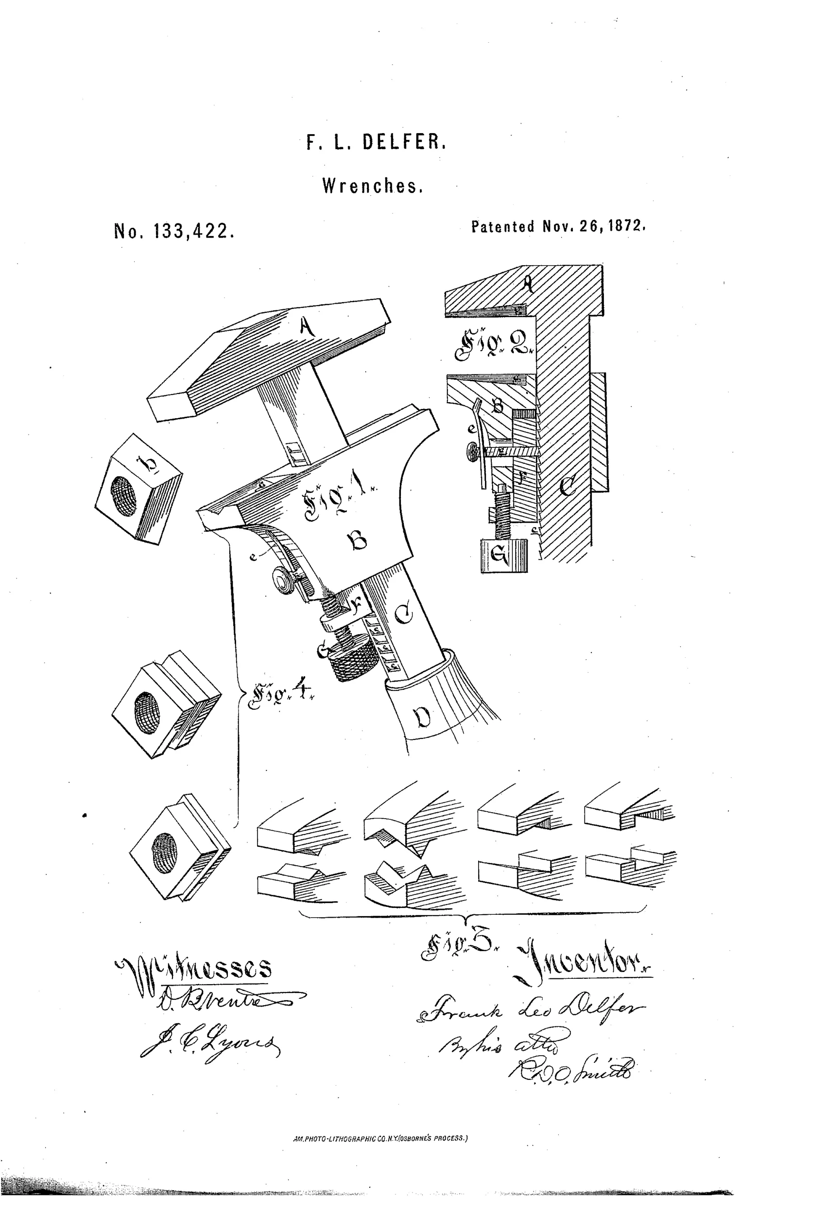
A stationary jaw A is fixed to a rack-bar C bearing a series of rack-teeth, while a movable jaw B slides along the bar and is held in position by a pawl E engaging the teeth. The pawl is jointed to a sliding bar F, which can be moved independently of the jaw by an adjusting screw G, allowing fine adjustment near the desired contact point. A spring e keeps the pawl engaged with the rack teeth, so the jaw may be slid quickly into rough position and then finely adjusted by the screw. The jaws also have specially shaped faces with angular recesses g to grip nuts of irregular or tapered form without requiring heavy pressure.
⚙ What was claimed
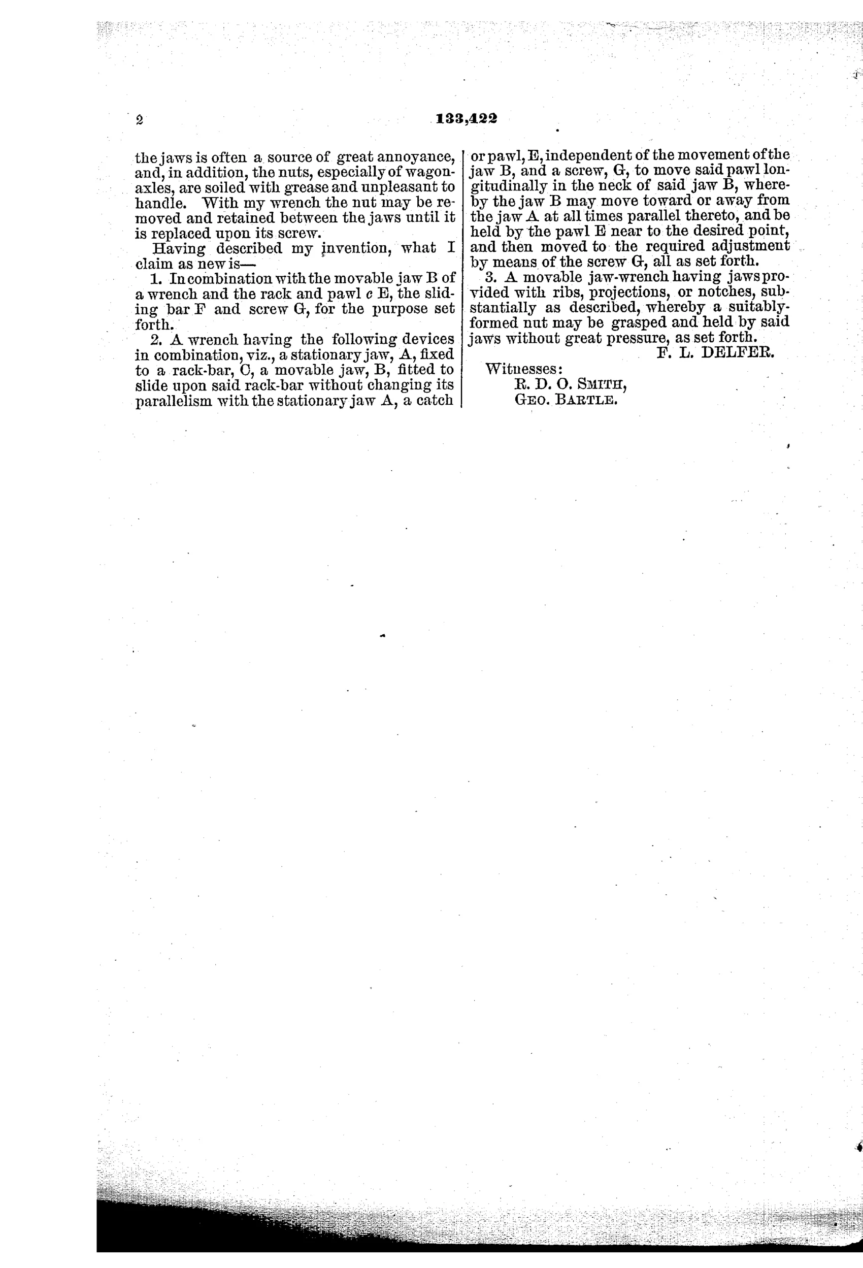
“2. A wrench having the following devices in combination, viz., a stationary jaw, A, fixed to a rack-bar, C, a movable jaw, B, fitted to slide upon said rack-bar without changing its parallelism with the stationary jaw A, a catch or pawl, E, independent of the movement of the jaw B, and a screw, G, to move said pawl longitudinally in the neck of said jaw B, whereby the jaw B may move toward or away from the jaw A at all times parallel thereto, and be held by the pawl E near to the desired point, and then moved to the required adjustment by means of the screw G, all as set forth.”
In plain English: The wrench combines a fixed jaw, a sliding jaw that stays parallel to it, and an independent pawl moved by a screw so the sliding jaw can be quickly positioned near a nut and then finely adjusted to fit snugly.
⚙ In the inventor’s words
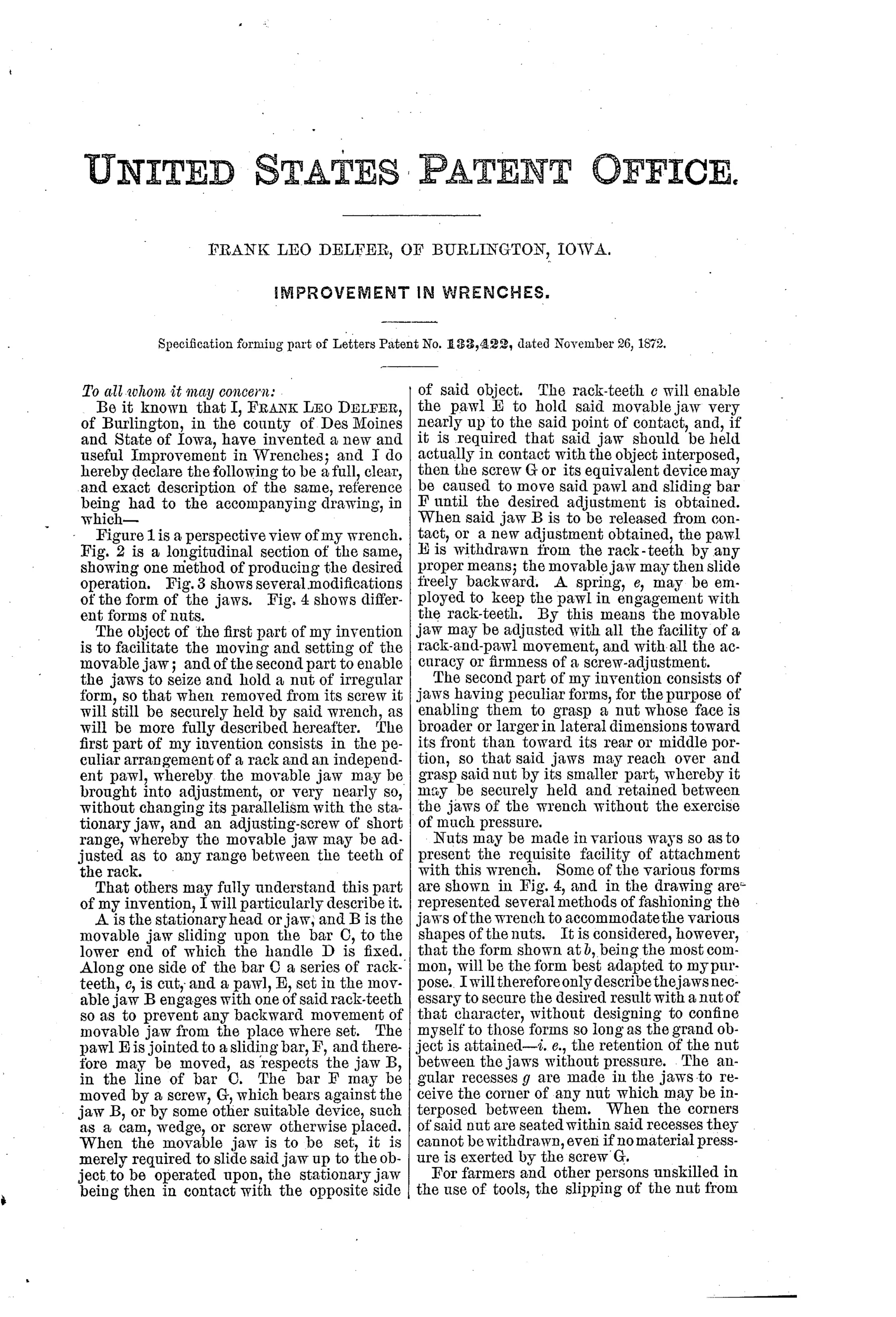
“With my wrench the nut may be removed and retained between the jaws until it is replaced upon its screw.”— Frank Leo Delfer, from the specification
Fate unknown
No catalogued Delfer wrench is known to me; a marked specimen or period hardware listing would settle it — DATAMP is the place to check.
⚙ Patented the same day
- IMPROVEMENT IN COMBINED CLAMPS AND WRENCHES. — Ephraim Maguire
- IMPROVEMENT IN WRENCHES — Ovide Bonneville
⚙ Commentary
Delfer's answer to the quick-adjust problem is a two-stage mechanism, and it's a genuinely thoughtful one. Slide the movable jaw B down the toothed rack-bar until the spring-loaded pawl E clicks in near the nut — that's the coarse move, done in a second. But a pawl on a rack can only land on tooth increments, and a wrench that's a sixteenth of an inch loose is a knuckle-buster. So Delfer joints the pawl to a sliding bar F and drives that bar with a small screw G, letting you close the last fraction of the gap smoothly. Coarse by pawl, fine by screw: the same logic that later appears in machinist's clamps and height gauges.
Fig. 2 rewards a close look — the section shows how the pawl floats independently of the jaw body, which is the whole trick. Fig. 3 is the sleeper, though: a row of alternate jaw faces with angular recesses meant to grip worn, tapered, or odd-shaped nuts, with Fig. 4 showing the offending nuts themselves. Delfer even claims the wrench can carry the nut off its bolt and back on — a small courtesy that anyone who has dropped a nut into machinery will appreciate.
It sits in the crowded 1870s hunt for one-hand speed that Coes's screw wrench couldn't offer. The mechanism would work; whether it could be built cheaply enough to beat a plain screw wrench is the harder question, and the record is silent.
Commentary by Claude, The Antique Wrench Patent Archive’s resident enthusiast