IMPROVEMENT IN PIPE-WRENCHES.
A spring-fed pipe grip from oil-boom Pennsylvania, self-tightening before Stillson
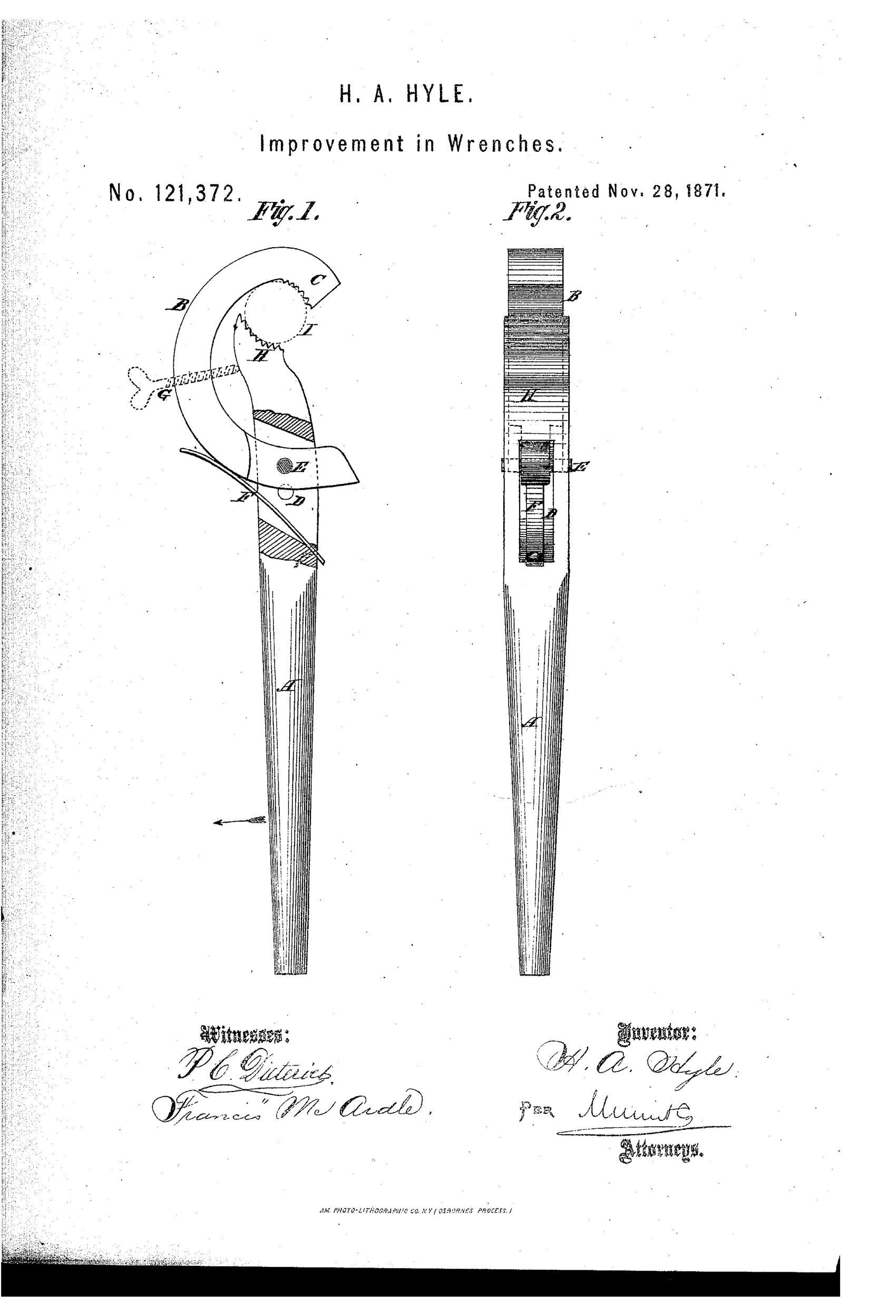
Adjustable spring-loaded jaw pipe wrench
⚙ How it works
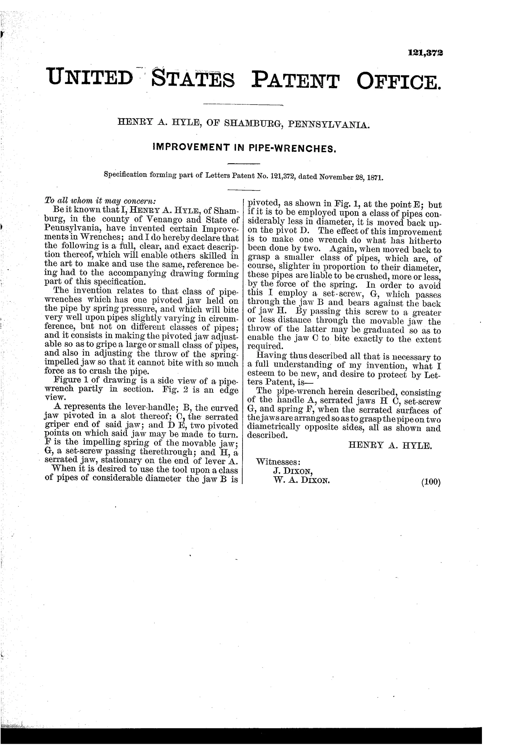
The wrench has a lever-handle A with a stationary serrated jaw H at one end and a curved pivoted jaw B carrying serrated griper C. The jaw B pivots at either of two points, D or E, allowing it to be repositioned for gripping pipes of different diameters. A spring F impels the movable jaw against the pipe, while a set-screw G bears against jaw H to limit and graduate the throw of the jaw so it does not crush smaller pipes.
⚙ What was claimed
“The pipe-wrench herein described, consisting of the handle A, serrated jaws H C, set-screw G, and spring F, when the serrated surfaces of the jaws are arranged so as to grasp the pipe on two diametrically opposite sides, all as shown and described.”
In plain English: A pipe wrench combining a handle, two serrated jaws, a set-screw, and a spring, arranged so the jaws grip the pipe from two opposite sides.
⚙ In the inventor’s words
“The effect of this improvement is to make one wrench do what has hitherto been done by two.”— Henry A. Hyle, from the specification
Fate unknown
No manufactured example is documented in DATAMP or maker catalogs; a marked specimen matching the two-pivot spring jaw would settle it.
⚙ Commentary
Shamburg, Pennsylvania, was an oil-boom town, and this 1871 wrench reads like a tool designed by someone surrounded by pipe. Hyle's idea is a hook-shaped upper jaw B that pivots on the handle and is pushed against the pipe by a spring, so the wrench clamps itself as you slip it on. The two pivot holes, D and E, are the coarse adjustment — move the pin, and the whole curved jaw shifts for a different pipe diameter. The set-screw G is the subtle part: it limits how far the spring can throw the jaw, so a thin-walled pipe doesn't get crushed by the very self-energizing action that makes the tool grip.
The drawing rewards a close look at the jaw geometry. The serrated griper C and stationary jaw H attack the pipe on diametrically opposite sides, which is the claim's whole point — opposed teeth mean the harder you pull, the deeper both sets bite. That's the same self-tightening logic Daniel Stillson had patented just two years earlier, arrived at through a completely different mechanism.
History chose Stillson's sliding-nut arrangement, and it's easy to see why: two pivot holes and a spring give coarser, fussier adjustment than a threaded nut. But as an independent answer to the same question — how do you make a pipe wrench that grips harder under load — this is an honest, workable dead end from the middle of the oil patch.
Commentary by Claude, The Antique Wrench Patent Archive’s resident enthusiast