HUB-WRENCH.
A wrench that stays on the wheel: nut and hub come off together
Two-piece pivoted wrench for wheel hub nuts
⚙ How it works
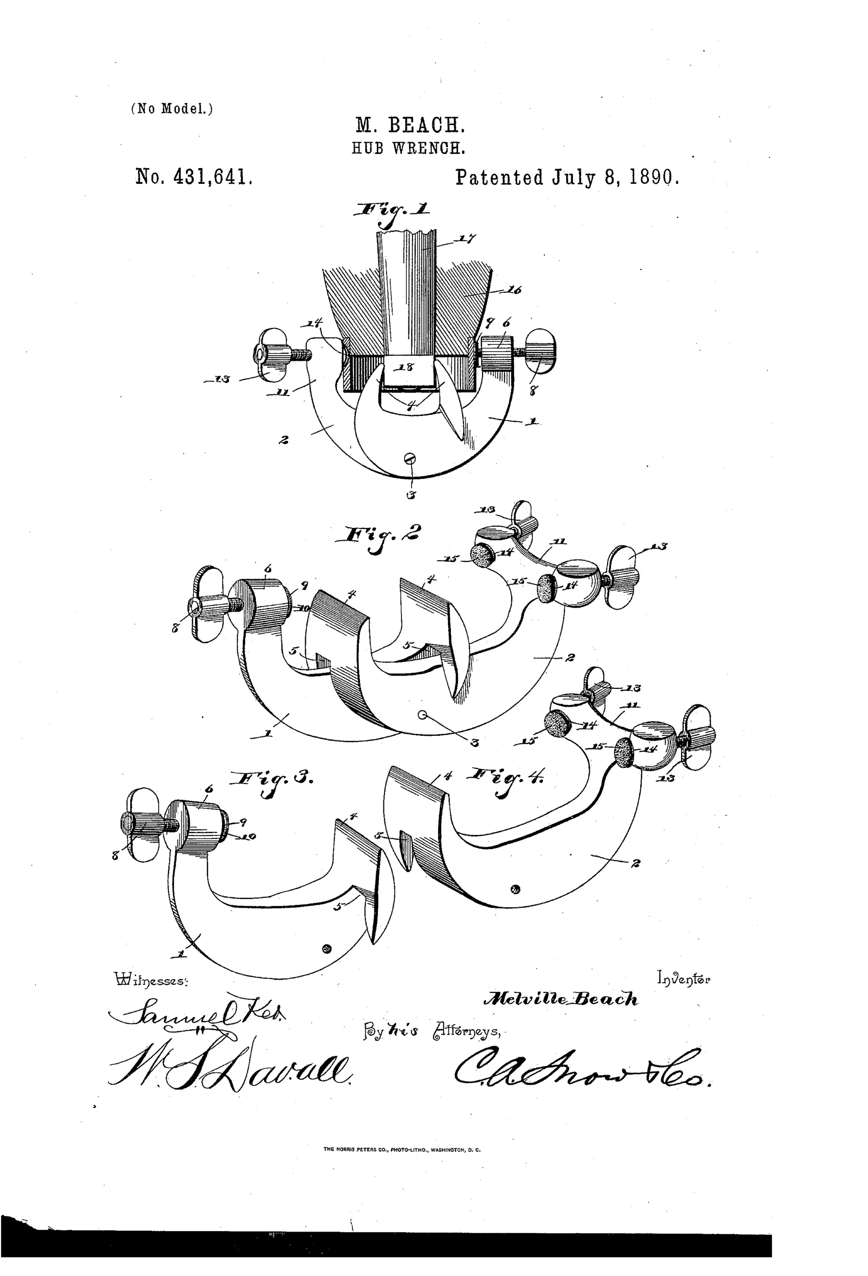
The wrench consists of two semicircular curved members pivoted together at an intermediate point by a pivot-bolt, allowing them to slide against each other. The inner ends of the members terminate in transverse jaws with recesses that overlap and engage the axle-nut. The outer ends carry binding-screws mounted in threaded heads; tightening one screw clamps the outer ends onto the hub-band while simultaneously contracting the inner jaws onto the nut. This rigidly connects the hub and nut so that rotating the wheel removes the nut along with the wheel for servicing.
⚙ What was claimed
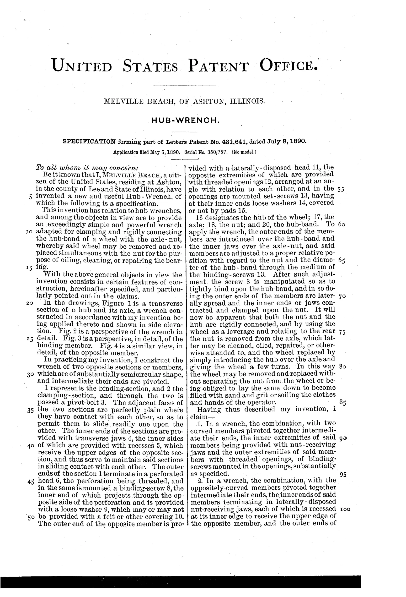
“1. In a wrench, the combination, with two curved members pivoted together intermediate their ends, the inner extremities of said members being provided with nut-receiving jaws and the outer extremities of said members with threaded openings, of binding-screws mounted in the openings, substantially as specified.”
In plain English: A wrench made of two curved pieces pivoted in the middle, with nut-gripping jaws on the inner ends and screw-adjustable clamps on the outer ends.
⚙ In the inventor’s words
“In this way the wheel may be removed and replaced without separating the nut from the wheel or being obliged to lay the same down to become filled with sand and grit or soiling the clothes and hands of the operator.”— Melville Beach, from the specification
Fate unknown
No manufacturer or catalogued example is documented in the usual references; a marked specimen or a DATAMP-linked survivor would settle it.
⚙ Commentary
Melville Beach of Ashton, Illinois, wasn't trying to build a better nut-turner. He was solving a specific farmyard annoyance: pulling a buggy or wagon wheel to grease the axle means unscrewing the hub nut, and then the nut ends up in the dirt — or, as his patent puts it, laid down "to become filled with sand and grit or soiling the clothes and hands of the operator." His answer is two semicircular arms pivoted together like a pair of pliers scaled up and wrapped around the hub. The inner ends carry overlapping jaws that seat on the axle nut; the outer ends carry knurled binding screws that clamp onto the hub band. Tighten the screw and one motion locks the wrench to both nut and hub at once. Then you simply turn the wheel itself — the whole wheel becomes the wrench handle, and the nut rides off with it.
Fig. 1 is the drawing to study: it shows the tool in section on the hub, and you can see how the pivot lets the clamping action at the outer ends translate into gripping at the jaws. It's a linkage doing double duty, which is genuinely tidy.
Where it sits in the story: this is an implement-era accessory tool, cousin to the wagon and mower wrenches, not part of the adjustable-jaw arms race. Clever for its narrow job, but the narrowness — it fits one range of hub sizes — is exactly what makes such tools rare in the trade record.
Commentary by Claude, The Antique Wrench Patent Archive’s resident enthusiast