VEHICLE-WRENCH.
Clamp the nut, hook the spokes, and let the wheel do the wrenching
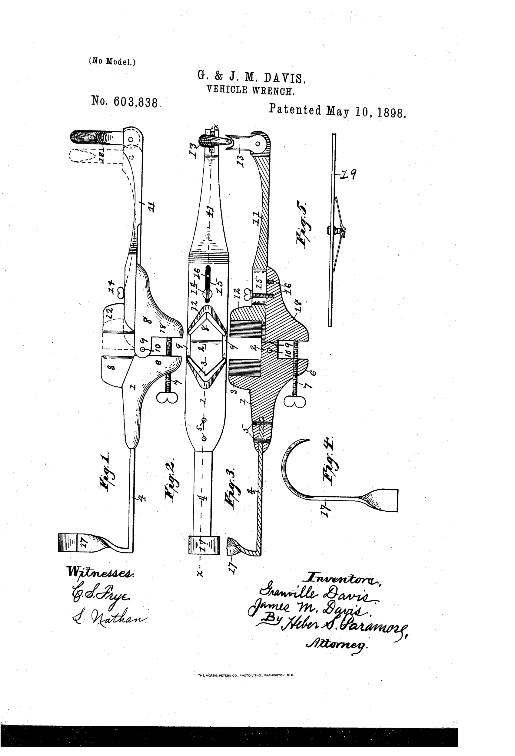
Combination axle-nut and wheel-spoke wrench
⚙ How it works
The wrench has two hinged, opposed jaw arms that clamp onto a vehicle axle-nut, with one arm slidably adjustable via a thumb-screw riding in a slot to fit different nut sizes. A flat spring-arm fixed to the base terminates in a right-angled hook that engages a wheel spoke, while the adjustable arm carries a pivoted hook that engages another spoke, holding the tool securely against the wheel. By rotating the wheel with the wrench so hooked, the axle-nut is forced to turn with the wheel, loosening or tightening it. If wheel-clamping is not desired, the jaws alone can be tightened directly onto the nut using the thumb-screw pressing against the jaw-support's extended face.
⚙ What was claimed
“A vehicle-wrench of the class described, consisting of the jaw-base 1, having the lug 2, the extended portion 6, carrying the thumb-screw 7, and the jaw 3, and having a spring-arm 4, fixedly secured thereto, said spring-arm terminating in a right-angled hook 17, a jaw-support 8, having lugs 9, and a projecting portion 18, is pivotally attached to the hinge-lug 2 by a pin or bolt 10. An adjustable arm 11, having an angular jaw 12 and carrying a pivotally-secured hook 13 at its outer end, is slidably secured upon the jaw-support 8 by means of a thumb-screw 14, passing through a slot 15 in the adjustable arm 11 and entering threaded openings 16 in the jaw-support 8.”
In plain English: The wrench is made of a jaw base with a fixed spring hook and an adjustable arm with a sliding jaw and pivoting hook, all connected so the jaws can be tightened around a nut while the hooks grip the wheel spokes.
⚙ In the inventor’s words
“By rotating the wheel the nut will be loosened or tightened, as the case may be, inasmuch as it is forced to turn with the wheel.”— Granville Davis and James M. Davis, from the specification
Fate unknown
No manufactured specimen is documented; a surviving marked wrench or a hardware catalog listing would settle it.
⚙ Commentary
The Davis brothers of North Salem, Indiana, looked at the miserable job of loosening a rusted axle-nut and decided the strongest lever on the whole vehicle was the wheel itself. Their wrench clamps onto the nut with two hinged jaws, then reaches out with a pair of hooks — one on a fixed spring-arm, one pivoted on the adjustable arm — to grab two spokes. Turn the wheel and the nut is forced to turn with it. Fig. 5 shows the whole scheme deployed on a wheel, and it's worth a close look: the tool essentially locks the nut to the wheel so the wheel's own leverage does the work.
Mechanically it's sound in principle. A wagon wheel gives you an enormous moment arm compared to any handle you could carry, and axle-nuts were notorious for seizing. The thumb-screw and slotted arm let the jaw span different nut sizes, and the same screw bearing on the jaw-support's extended face lets you use it as a plain adjustable wrench when the spoke-hooking business isn't wanted.
The doubt is practical: that's a lot of hinges, slots, and pivoted hooks for a farm tool, and the spring-arm hook has to hold under real torque. It sits in the crowded 1890s field of buggy and implement wrenches — a clever dead end rather than a refinement anyone built on. DATAMP records the patent; I know of no marked example.
Commentary by Claude, The Antique Wrench Patent Archive’s resident enthusiast