IMPROVEMENT IN WRENCHES
Bedell swaps flat bar faces for angular bearings to fight monkey-wrench wobble
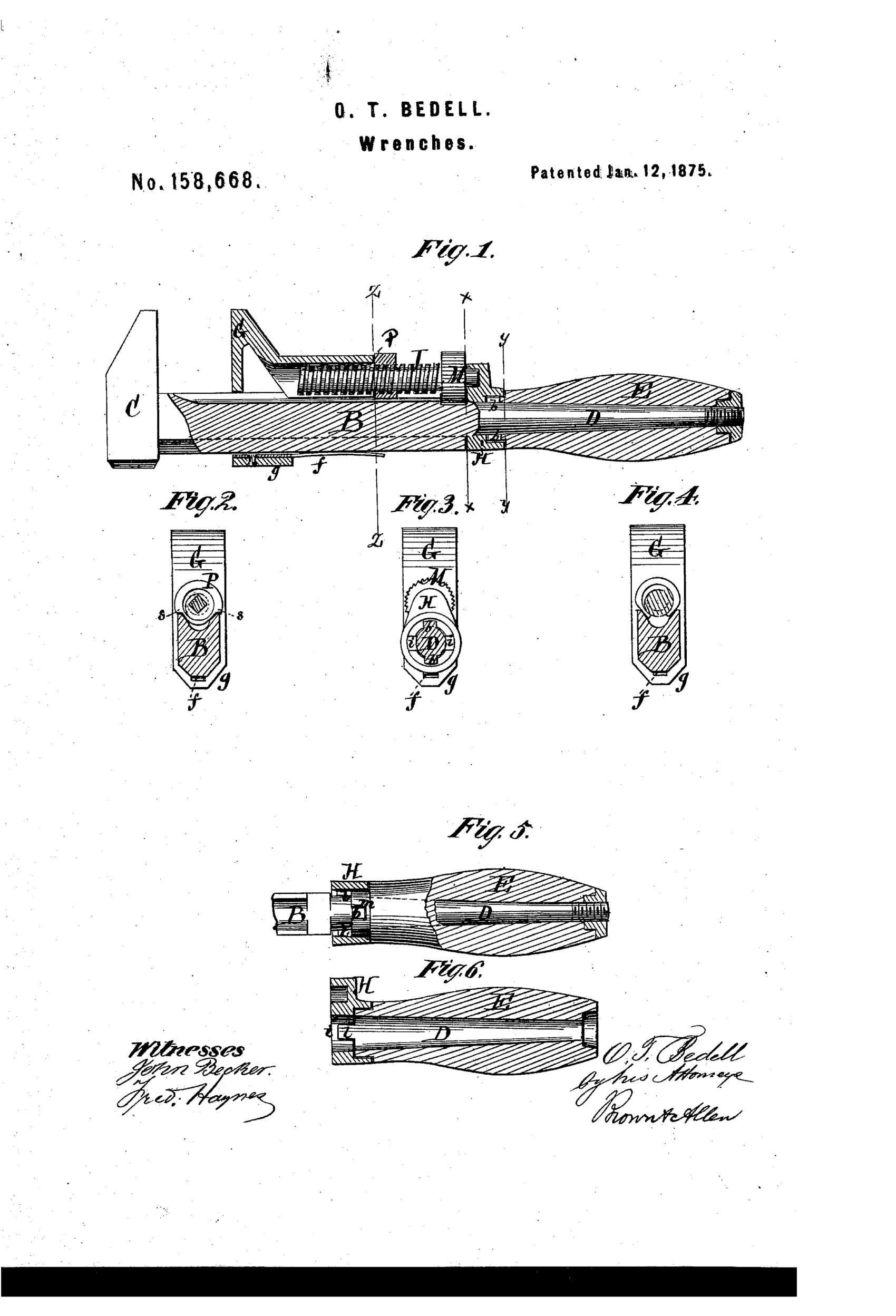
Adjustable screw wrench with angular bar and jaw
⚙ How it works
A main bar has a convex angular back edge and a concave angular front edge, forming a hexagonal-like bearing surface. The movable jaw has a keeper that surrounds the bar and matches its angular back edge, while its tubular portion is open at the bottom to fit the concave front edge without friction. A milled-head screw turns a threaded carriage or nut along the bar, sliding the jaw toward or away from the fixed jaw. A friction spring in the keeper holds the jaw steady until pressure from the carriage is applied, and a combined ferrule and pressure-bar with lugs and notches locks the handle onto the bar shank.
⚙ What was claimed
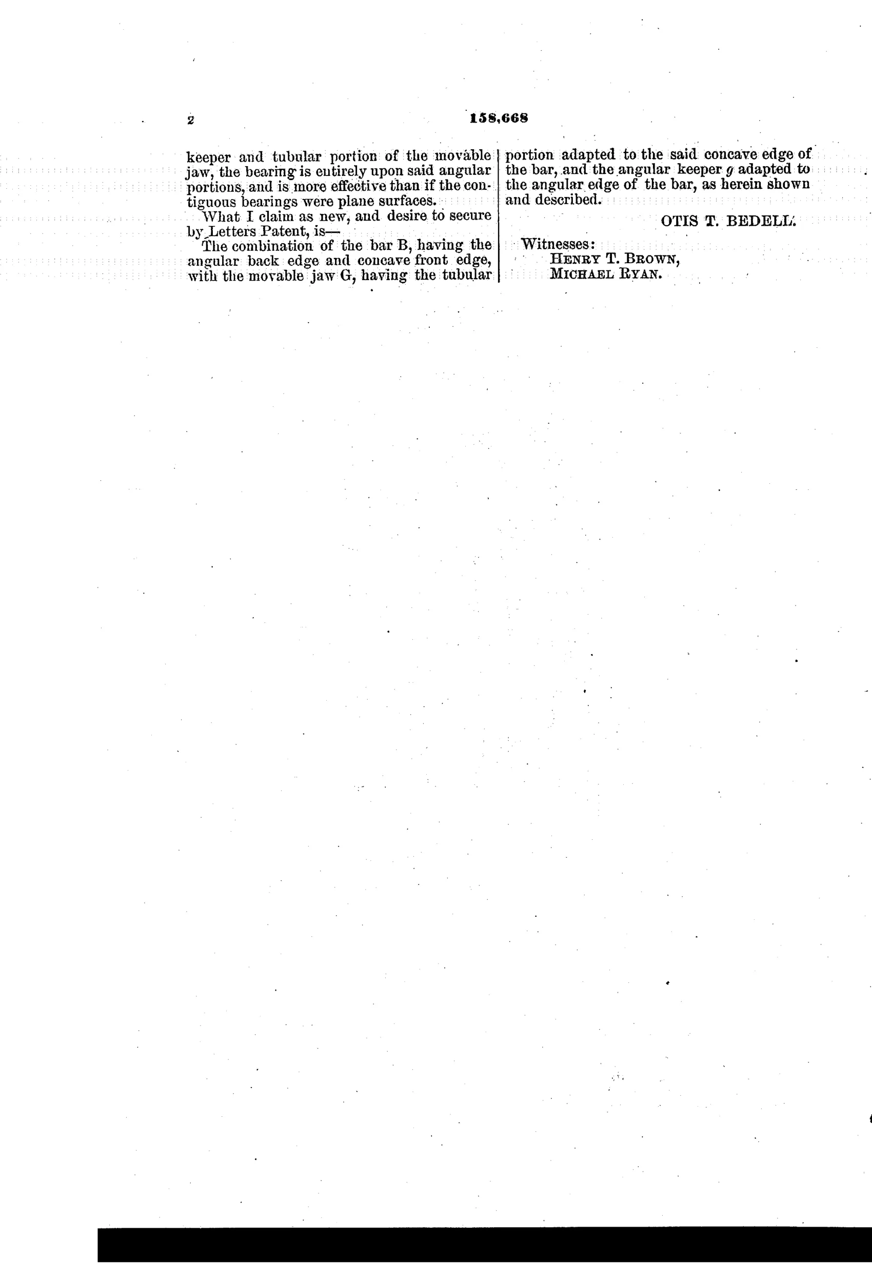
“The combination of the bar B, having the angular back edge and concave front edge, with the movable jaw G, having the tubular portion adapted to the said concave edge of the bar, and the angular keeper g adapted to the angular edge of the bar, as herein shown and described.”
In plain English: The invention claims a wrench bar with an angular back and concave front edge combined with a movable jaw whose tubular part fits the concave edge and whose keeper fits the angular back edge.
⚙ In the inventor’s words
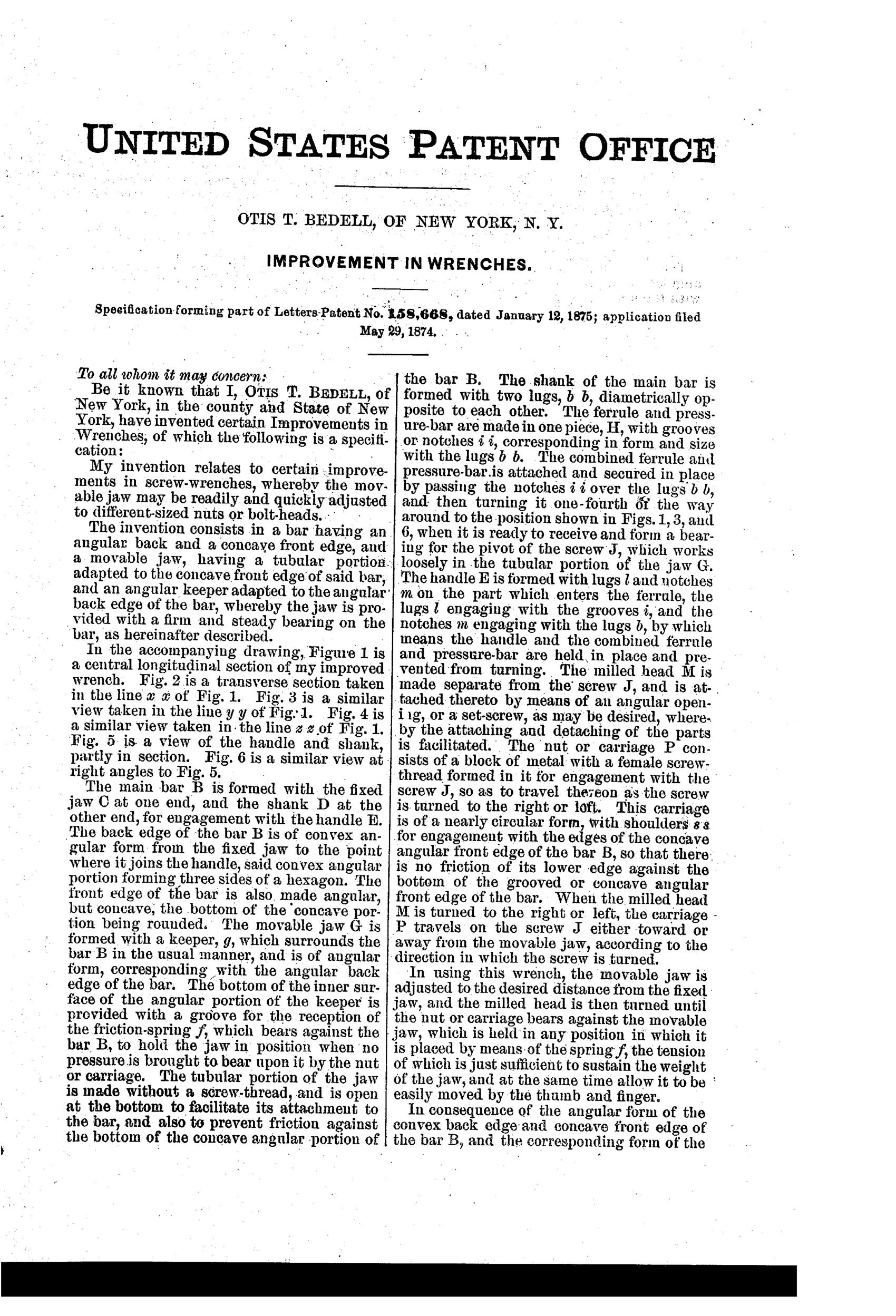
“In consequence of the angular form of the convex back edge and concave front edge of the bar B, and the corresponding form of the keeper and tubular portion of the movable jaw, the bearing is entirely upon said angular portions, and is more effective than if the contiguous bearings were plane surfaces.”— Otis T. Bedell, from the specification
Fate unknown
No manufactured Bedell wrench of this pattern is documented in the usual references; a marked specimen or a DATAMP-linked catalog entry would settle it.
⚙ Commentary
The problem every screw wrench of this era wrestled with is play: a sliding jaw on a flat rectangular bar rocks under load, and every bit of rock is lost grip on the nut. Bedell's answer is geometric. His bar B has a convex angular back edge and a concave angular front edge — look at the cross-sections in Figs. 2-4 and you can see the near-hexagonal profile. The keeper on the movable jaw matches the angular back; the tubular portion nests into the concave front. His own specification says it plainly: the bearing falls entirely on those angular portions, which self-center the jaw far better than plane surfaces sliding on plane surfaces.
The rest of the wrench is standard Coes-family practice — a milled-head screw driving a threaded carriage along the bar — but there are two thoughtful extras. A friction spring in the keeper holds the jaw steady until the carriage actually pushes it, so the jaw doesn't rattle down the bar when you tip the tool. And Figs. 5 and 6 show a lugged ferrule-and-pressure-bar arrangement locking the wooden handle to the shank, a fussier joint than most makers bothered with.
It's a refinement, not a revolution, in a decade drowning in wrench patents. But the angular-bearing idea is genuinely sound engineering — the same self-locating logic as a V-way on a lathe bed — even if it meant costlier forging and machining than a plain flat bar.
Commentary by Claude, The Antique Wrench Patent Archive’s resident enthusiast