AUTOMATIC SELF-SETTING WRENCH
Roller-and-incline wedge lock: back-pressure tightens the jaw instead of loosening it
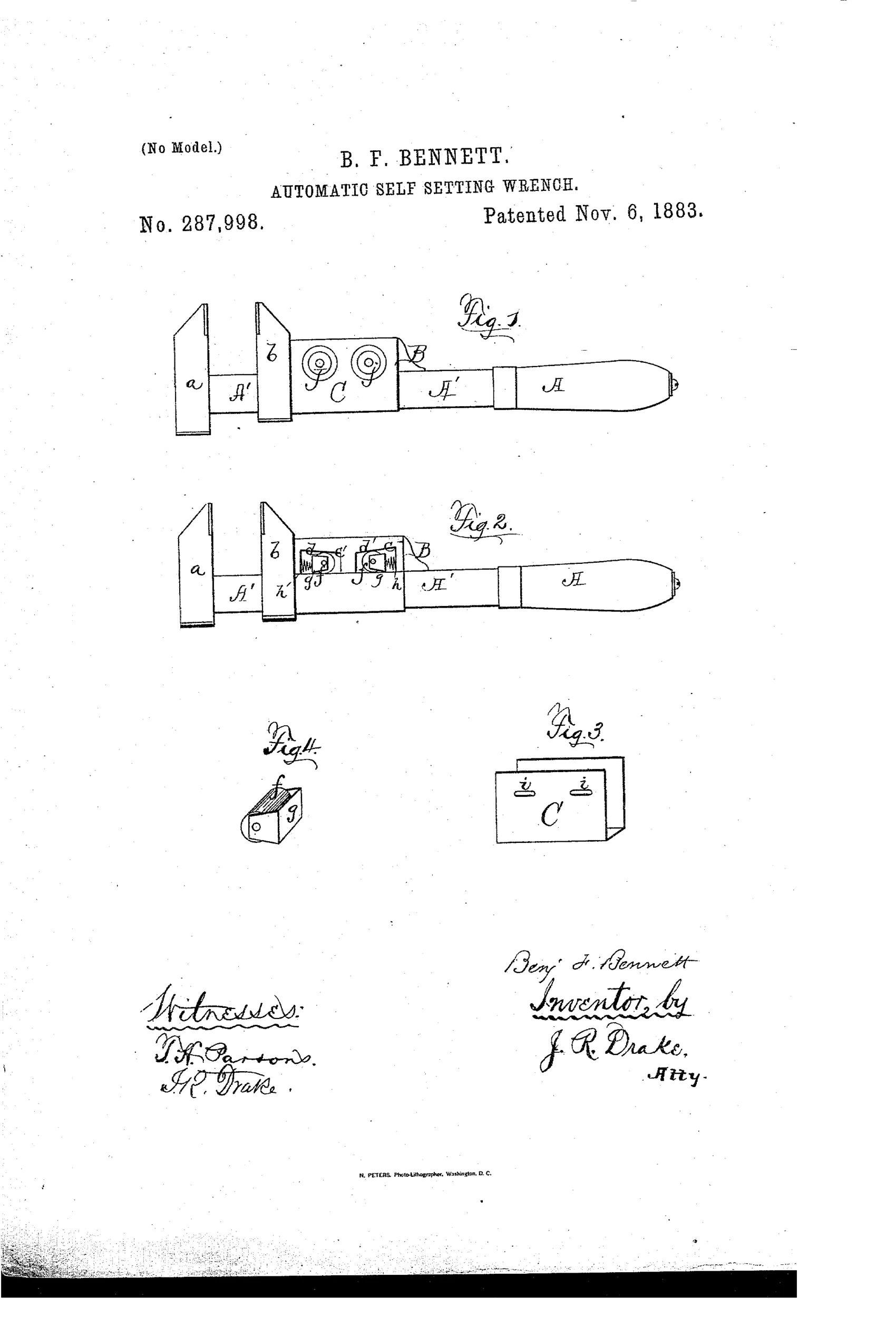
Self-tightening wrench with spring-loaded roller lock
⚙ How it works
A movable jaw slides on a short bar that carries one or two chambers with inclined upper surfaces. Metal rollers ride in follower frames within these chambers, biased by coiled springs toward the narrow end of each incline. Backward pressure on the movable jaw forces the rollers into the narrow part of the chamber, wedging and locking the jaw tighter automatically. Pulling or pushing buttons connected to the roller shafts, which protrude through slots in a covering plate, releases the rollers into the enlarged part of the chamber to allow the jaw to be adjusted.
⚙ What was claimed
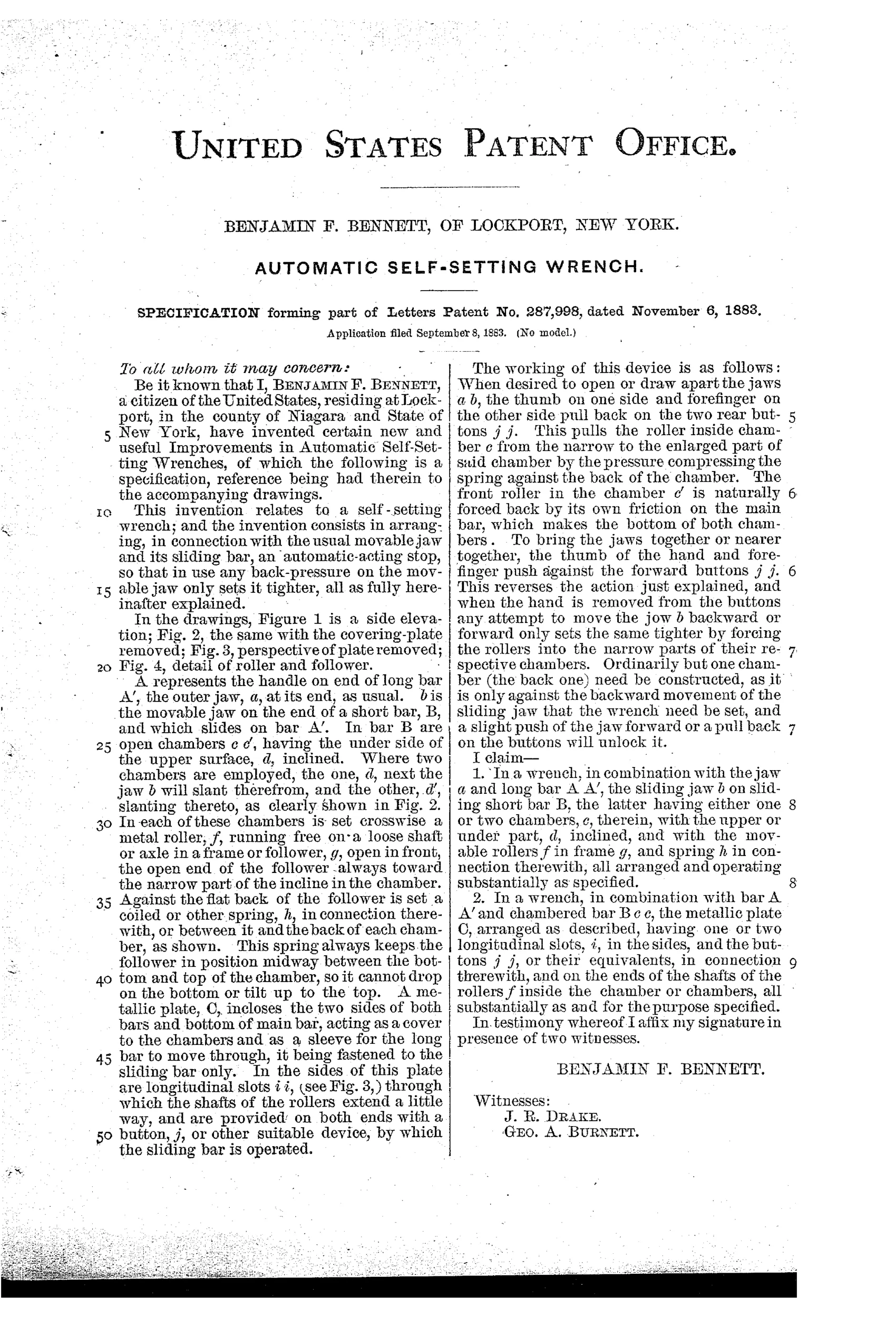
“In a wrench, in combination with the jaw a and long bar A A', the sliding jaw b on sliding short bar B, the latter having either one or two chambers, c, therein, with the upper or under part, d, inclined, and with the movable rollers f in frame g, and spring h in connection therewith, all arranged and operating substantially as specified.”
In plain English: The wrench combines a fixed jaw and a sliding jaw on a bar with one or two inclined chambers containing spring-loaded rollers that automatically lock the sliding jaw in place.
⚙ In the inventor’s words
“The invention consists in arranging, in connection with the usual movable jaw and its sliding bar, an automatic-acting stop, so that in use any back-pressure on the movable jaw only sets it tighter, all as fully hereinafter explained.”— Benjamin F. Bennett, from the specification
Fate unknown
No catalogued production example is known to me; a marked specimen or a DATAMP-documented survivor would settle it.
⚙ Commentary
Bennett's mechanism is a roller clutch before that term was common. Inside the sliding bar that carries the movable jaw sit one or two chambers with inclined ceilings; a steel roller in each, pushed by a coil spring toward the narrow end. Squeeze the jaws onto a nut, pull the handle, and the reaction force drives the rollers up the incline where they wedge — the harder you pull, the tighter the grip. It is the same principle a modern sprag clutch or a one-way bearing uses, worked out in a hand tool in 1883.
Fig. 2 is the view worth studying: with the cover plate off you can see the twin roller frames and their springs, plus the little buttons on the roller shafts that poke through slots in the plate (Fig. 3). Slide the buttons back and the rollers drop into the wide end of the chamber, freeing the jaw for one-hand adjustment. That release is the clever part and also the weak spot — rollers wedged under full wrenching load do not let go politely, and grit or a burred incline would make the whole thing sticky.
This sits squarely in the 1880s rush toward quick-adjust, self-gripping wrenches, the field's great obsession. Most of those entries died on paper because a plain Coes screw wrench was cheaper and never slipped in a way the user couldn't feel. Bennett's is more elegant than most, but elegance in a chamber full of small rollers and springs is expensive to machine.
Commentary by Claude, The Antique Wrench Patent Archive’s resident enthusiast