Pipe-Wrench.
A loose slide, attached to nothing, does all the locking work
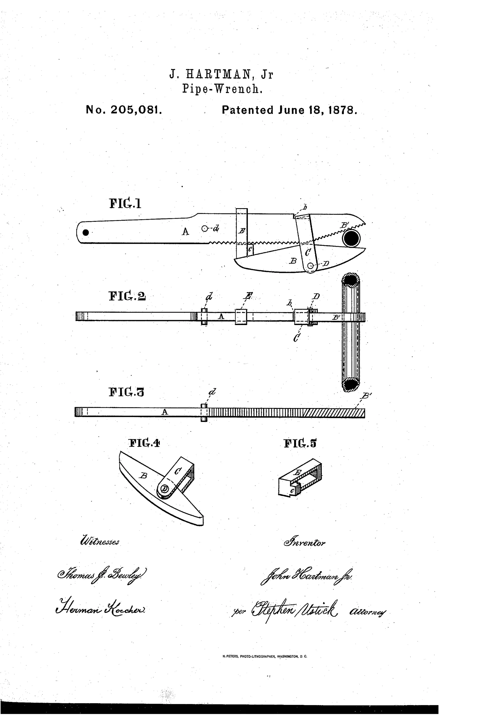
An improved pipe wrench with removable clamping slide
⚙ How it works
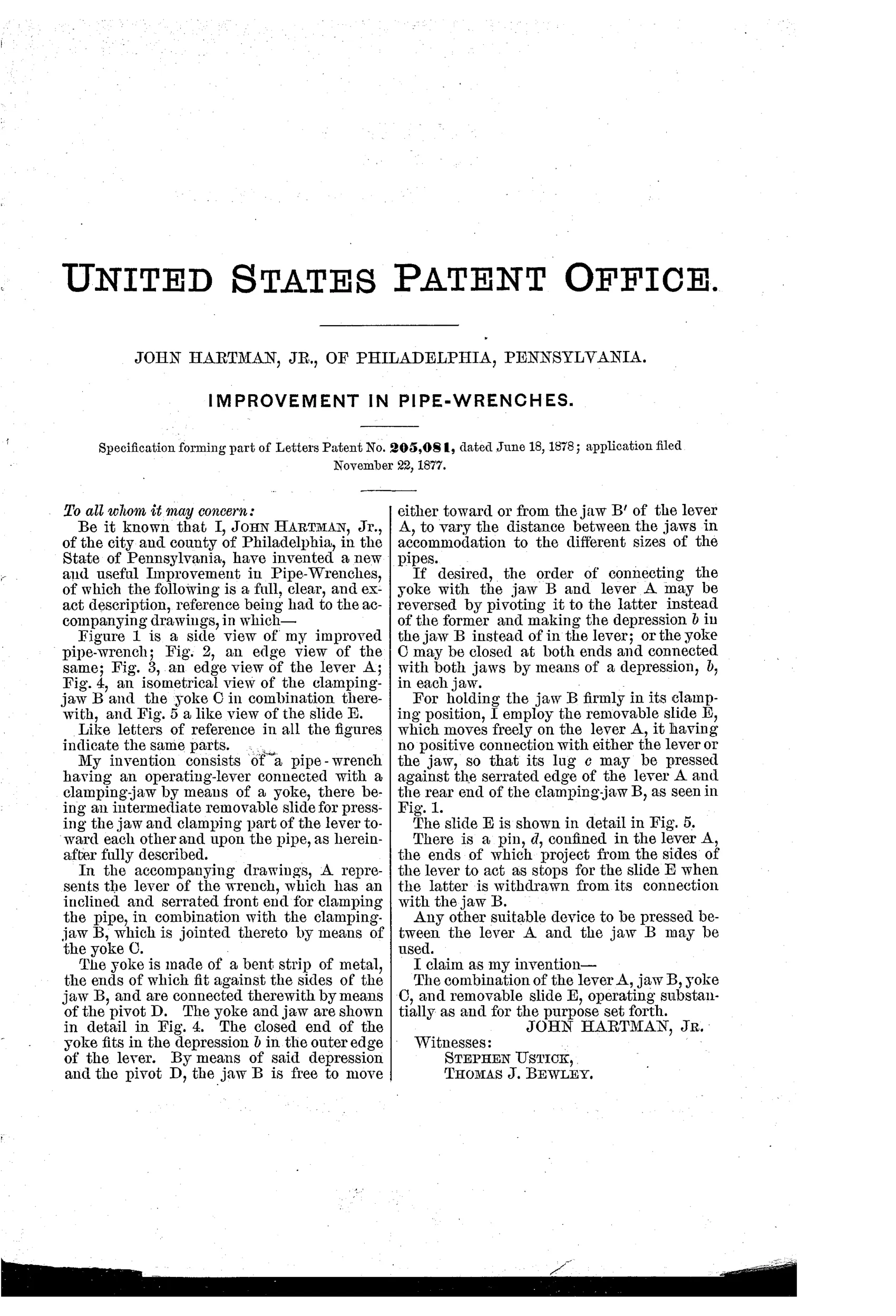
A serrated lever A pivots against a hinged clamping jaw B, which is linked to the lever by a bent-metal yoke C connected via a pivot D. The yoke's closed end fits into a depression b on the outer edge of the lever, allowing the jaw to swing toward or away from the lever's jaw B' to fit different pipe sizes. A removable slide E rides freely on the lever, unattached to either the lever or jaw, so its lug c can be pressed between the serrated edge of lever A and the rear end of jaw B to lock the clamp firmly onto the pipe. A pin d fixed in the lever projects from its sides to act as stops that keep the slide E from sliding off when withdrawn from its connection with jaw B.
⚙ What was claimed
“The combination of the lever A, jaw B, yoke C, and removable slide E, operating substantially as and for the purpose set forth.”
In plain English: The invention claims the combined lever, clamping jaw, connecting yoke, and a removable slide that together tighten the wrench onto a pipe.
⚙ In the inventor’s words
“For holding the jaw B firmly in its clamping position, I employ the removable slide E, which moves freely on the lever A, it having no positive connection with either the lever or the jaw, so that its lug c may be pressed against the serrated edge of the lever A and the rear end of the clamping-jaw B, as seen in Fig. 1.”— John Hartman, Jr., from the specification
Fate unknown
No manufactured example or catalogue listing is documented at DATAMP or elsewhere that I know of; a marked specimen would settle it.
⚙ Commentary
Hartman's wrench is built around a small act of mechanical faith. The serrated lever A and the hinged jaw B do the gripping, connected by a bent yoke C that hooks into a notch on the lever's back edge. But nothing in that arrangement actually locks the grip. That job falls to the slide E — a little rectangular collar that rides freely on the lever, deliberately unattached to anything, which the user shoves forward so its lug wedges between the lever's toothed edge and the tail of the jaw. Friction and geometry do the rest.
The drawing rewards a close look. Fig. 5 shows the slide in isolation: a plain folded-metal box with one internal lug, about as cheap a locking element as can be imagined. And the pin d in Fig. 3 is the honest detail — Hartman knew a free-floating part would slide right off the handle, so he added stops to trap it. That's an inventor patching his own design's weakness on the same sheet.
As pipe wrenches go, this sits in the crowded 1870s middle ground before Stillson-pattern wrenches settled the question. The wedge-lock would probably hold under load — clamping force tends to tighten it — but adjusting to a new pipe size means fiddling with three loose relationships at once. A Stillson does the same job with one nut. Workmanlike, clever in its economy, and almost certainly outrun by simpler competitors.
Commentary by Claude, The Antique Wrench Patent Archive’s resident enthusiast