IMPROVEMENT IN PIPE-WRENCHES
An 1871 cam-grip pipe wrench with a built-in stop against crushing the pipe
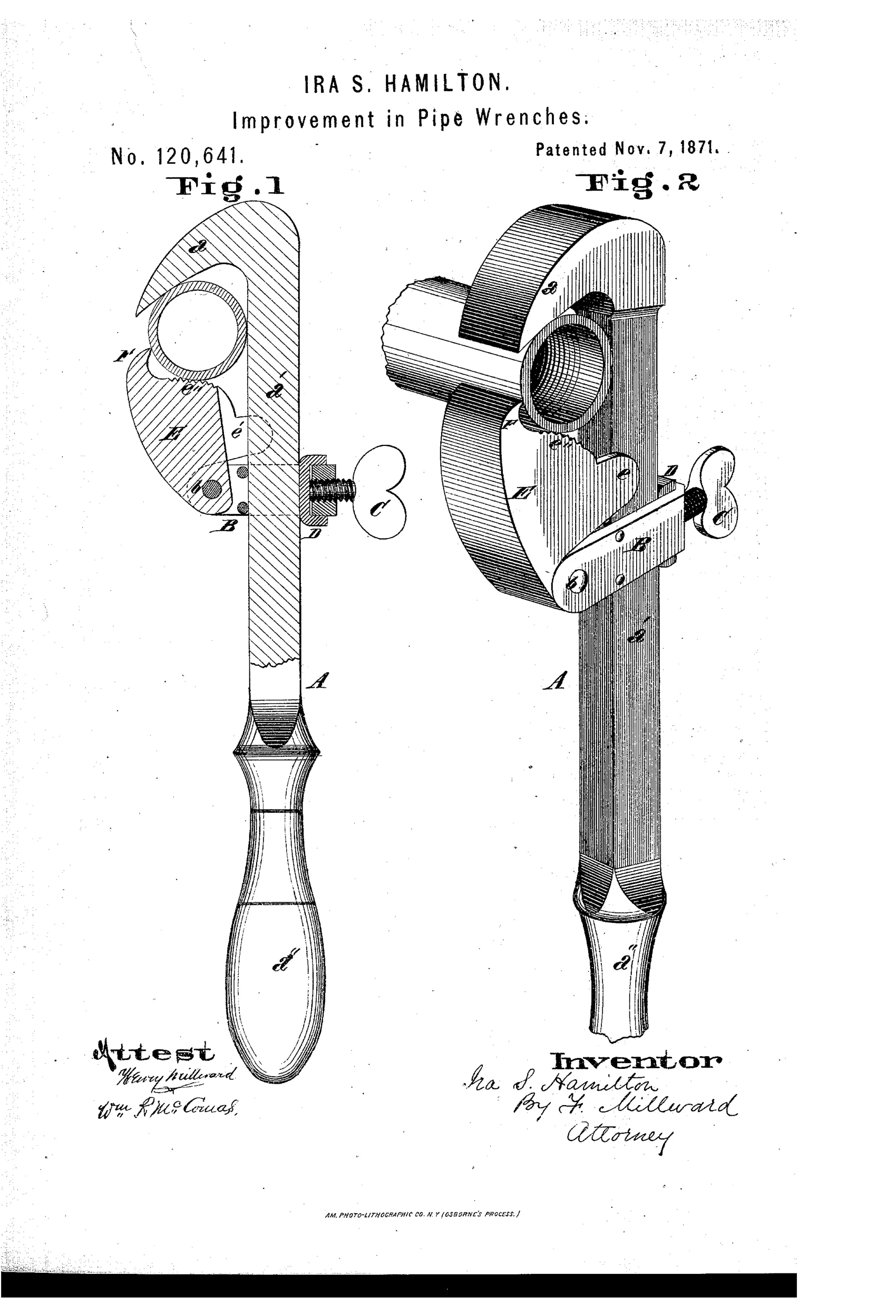
Self-tightening pipe wrench with adjustable pivoting cam jaw
⚙ How it works
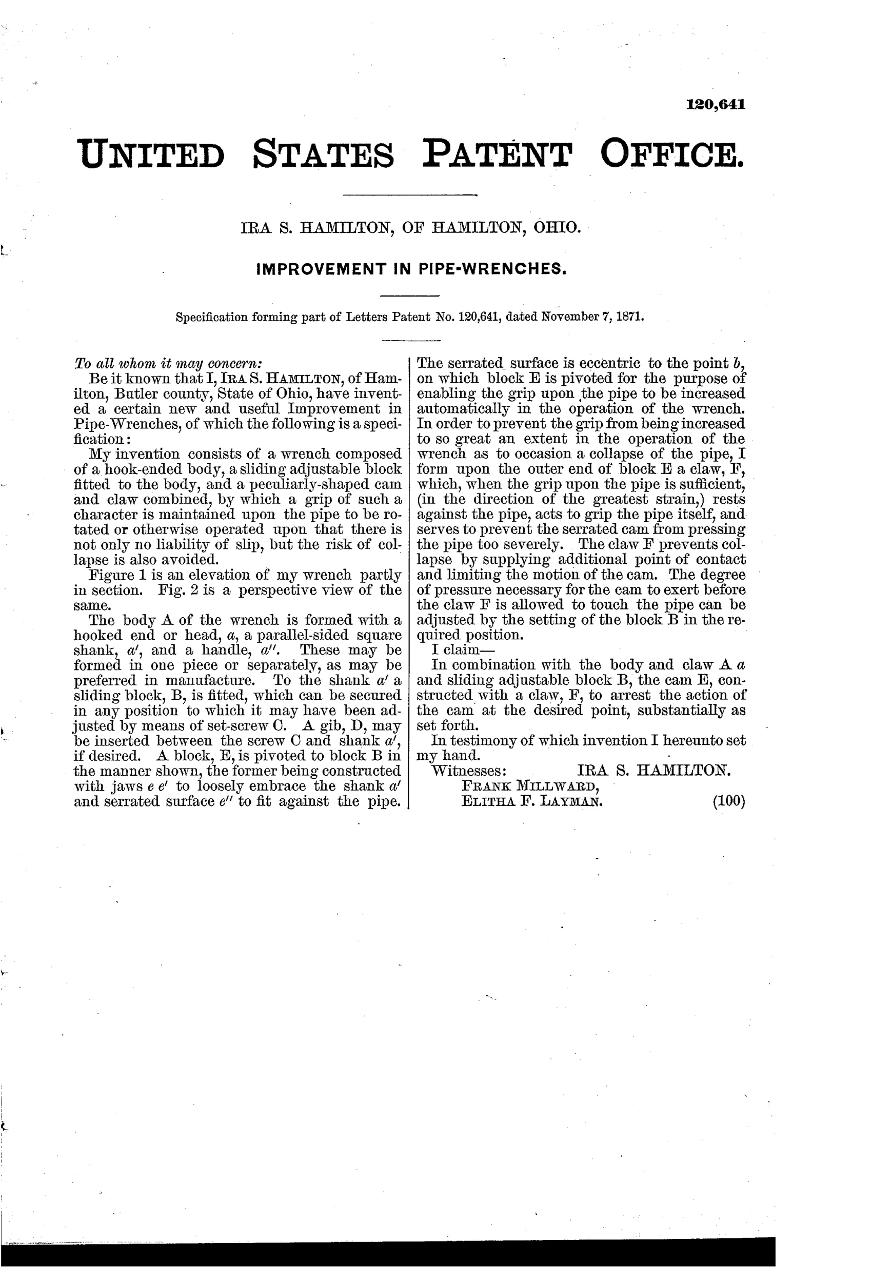
The wrench body A has a hooked head a, a square shank a', and a handle a''. A sliding block B is fitted to the shank and secured by a set-screw C, with an optional gib D. Block E is pivoted to block B and has jaws that loosely embrace the shank, with a serrated surface e'' set eccentric to pivot point b that bears against the pipe. This eccentricity causes the grip on the pipe to automatically increase as the wrench is turned, while a claw F on the outer end of block E contacts the pipe to limit the cam's action and prevent the pipe from being crushed.
⚙ What was claimed
“In combination with the body and claw A a and sliding adjustable block B, the cam E, constructed with a claw, F, to arrest the action of the cam at the desired point, substantially as set forth.”
In plain English: The wrench combines a hooked body with a sliding adjustable block and a pivoting cam that has its own claw to stop the cam from over-gripping the pipe.
⚙ In the inventor’s words
“My invention consists of a wrench composed of a hook-ended body, a sliding adjustable block fitted to the body, and a peculiarly-shaped cam and claw combined, by which a grip of such a character is maintained upon the pipe to be rotated or otherwise operated upon that there is not only no liability of slip, but the risk of collapse is also avoided.”— Ira S. Hamilton, from the specification
Fate unknown
No manufactured example or catalog listing is documented; a marked specimen would settle it.
⚙ Patented the same day
- IMPROVEMENT IN WRENCHES. — Alonzo Whitcomb
⚙ Commentary
Self-tightening pipe wrenches were the problem of the moment in 1871 — Daniel Stillson's famous design was only a couple of years old — and Ira Hamilton of Hamilton, Ohio took his own run at it. His answer is a hooked head opposed by a pivoting cam block E, whose serrated face is deliberately set eccentric to its pivot. Turn the wrench and geometry does the rest: the harder you pull, the deeper the cam bites. That much is standard self-tightening logic.
What sets this one apart is the claw F on the outer end of the cam, and it is the whole point of the single claim. Cam grips have a vice: on thin-walled iron or lead pipe, an unlimited eccentric will keep rotating and squeeze until the pipe collapses. Hamilton's claw swings around and lands on the pipe itself, arresting the cam at a fixed depth of bite. It is a mechanical governor for grip pressure, and it shows a plumber's-eye understanding of the actual failure mode.
The rest is more ordinary — coarse adjustment by a sliding block on a square shank, locked with a set-screw and an optional gib. That set-screw is the design's weakness: you must fuss with it for every pipe size, exactly the tedium Stillson's knurled nut avoided. Figure 2's perspective shows how the cam's jaws straddle the shank loosely, letting it float into grip. A thoughtful dead end, but the anti-crush idea was a real insight. Documented at DATAMP.
Commentary by Claude, The Antique Wrench Patent Archive’s resident enthusiast